
Page 482 - Engineering Digital Design
P. 482
452 CHAPTER 10 / INTRODUCTION TO SYNCHRONOUS STATE MACHINE DESIGN
State
variable Input logic
State change value
variable, Q
Q. t
0 Reset Hold
Q, Hold
0 -»• 1 1
Q, Toggle Toggle
1 -»• 0 1
Operation (^ 1 ^ Q,it 1 0 Set Hold
Table
Excitation
(a) f Table
State (c)
Diagram
(b)
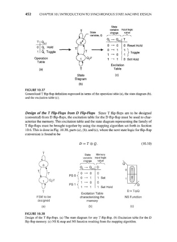
FIGURE 10.37
Generalized T flip-flop definition expressed in terms of the operation table (a), the state diagram (b),
and the excitation table (c).
Design of the T Flip-Flops from D Flip-Flops Since T flip-flops are to be designed
(converted) from D flip-flops, the excitation table for the D flip-flop must be used to char-
acterize the memory. This excitation table and the state diagram representing the family of
T flip-flops must be brought together by using the mapping algorithm set forth in Section
10.6. This is done in Fig. 10.38, parts (a), (b), and (c), where the next state logic for flip-flop
conversion is found to be
D = T®Q. (10.10)
State Memory
variable input logic
change value
Q D
0
PSO<°^ ° 1Q t
0 -* 1 1 Set
1 -> 0
PS 1 <! ' " °
1 -> 1 1 Set Hold
Excitation Table
characterizing the
memory
(b) (c)
FIGURE 10.38
Design of the T flip-flops, (a) The state diagram for any T flip-flop, (b) Excitation table for the D
flip-flop memory, (c) NS K-map and NS function resulting from the mapping algorithm.