
Page 500 - Engineering Digital Design
P. 500
470 CHAPTER 10 / INTRODUCTION TO SYNCHRONOUS STATE MACHINE DESIGN
outputs A(H), #(H), and C(H), where Q A = A, Q B = B, and Q C = C, and the Mealy
output Z is issued from the AND gate in state 111 but only when input X is active, i.e.,
only when the counter is in an up-count mode. The block symbol for this counter is shown
in Fig. 10.58b.
D K-map to T K-map Conversion Once the NS D K-maps have been plotted, it is
unnecessay to apply the mapping algorithm a second time to obtain the NS T K-maps. All
that is necessary is to use the D —>• T flip-flop conversion equation, Eq. (10.10), but written
as
D= Q®T = QT + QT. (10.18)
Applied to the individual state variables in a D -» T K-map conversion process, Eq. (10.18)
takes on the meaning
(10.19)
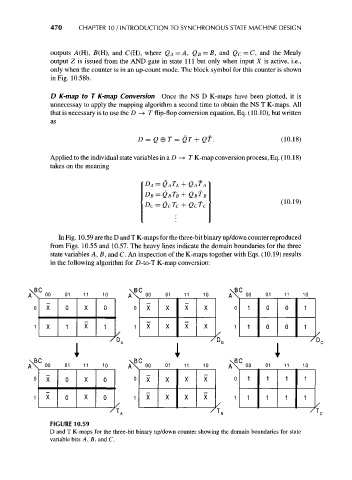
In Fig. 10.59 are the D and T K-maps for the three-bit binary up/down counter reproduced
from Figs. 10.55 and 10.57. The heavy lines indicate the domain boundaries for the three
state variables A, B, and C. An inspection of the K-maps together with Eqs. (10.19) results
in the following algorithm for D-to-T K-map conversion:
\BC \BC \BC
AX oo 01 11 10 A\ °° 01 11 10 A\ oo . 01 11 10
0 X 0 X 0 0 X X X X 0 1 0 0 1
1 X 1 X 1 1 X X X X 1 1 0 0 1
^o /
1 • 1 • i
/ D.
' 7
\BC \BC \BC
AX 00 01 11 10 AX 00 01 11 10 A\ 00 01 11 10
0 X 0 X 0 0 X X X X 0 1 1 1 1
1 X 0 X 0 1 X X X X 1 1 1 1 1
/ /
FIGURE 10.59
D and T K-maps for the three-bit binary up/down counter showing the domain boundaries for state
variable bits A, B, and C.