
Page 503 - Engineering Digital Design
P. 503
10.12 DESIGN OF SIMPLE SYNCHRONOUS STATE MACHINES 473
\
BC
D A\T oo 01 11 10
0
0 0 0 0
0
1 -•> 0 0 (t X (f) )
1 -> 1 1 ^
' ' ' ' 7 z
Excitation Table Output K-map
(a) (b)
\BC \BC \BC 01 11 1
A\ oo 01 11 10 A\ oo 01 11 10 X\ 0° Q
0 0 0 "xj
$ t 0 4 /
'D c
NS D K-maps
(c)
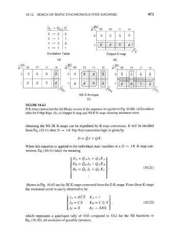
FIGURE 10.62
D K-map construction for the Mealy version of the sequence recognizer in Fig. 10.60c. (a) Excitation
table for D flip-flops, (b), (c) Output K-map and NS D K-maps showing minimum cover.
obtaining the NS JK K-maps can be expedited by K-map conversion. It will be recalled
from Eq. (10.11) that D -> JK flip-flop conversion logic is given by
D = QJ + QK.
When this equation is applied to the individual state variables in a D —> JK K-map con-
version, Eq. (10.11) takes the meaning
+
(10.21)
Shown in Fig. 10.63 are the JK K-maps converted from the D K-maps. From these K-maps
the minimum cover is easily observed to be
J A = BCX K A = 1
/~r v v s~i
y /? — UA /Yg — C (10.22)
J c = X K c = ABX
which represents a gate/input tally of 4/10 compared to 5/12 for the NS functions in
Eq. (10.20), all exclusive of possible inverters.