
Page 508 - Engineering Digital Design
P. 508
478 CHAPTER 10/INTRODUCTION TO SYNCHRONOUS STATE MACHINE DESIGN
converted to D K-maps as shown in Fig. 10.66b. Here, use is made of Algorithm 10.2 for
the reverse conversion process, that is, for the JK-to-D K-map conversion. Notice that the
domain boundaries are indicated by heavy lines as was done in Fig. 10.63.
Step 4 in the analysis procedure, given previously, requires the construction of the PS/NS
table from the D K-maps that are provided in Fig. 10.66b. This is done in Fig. 10.67a, from
which the state diagram follows directly as shown in Fig. 10.67b.
There are no serious problems with this FSM other than the potential to produce an output
race glitch (ORG) as a result of the transition 10 -> 01 under branching condition X. The
problem arises because two state variables are required to change during this transition, but
do not do so simultaneously. The result is that the FSM must transit from state 10 to 01 via
one of two race states, 00 or 1 1 . If the transition is by way of state 00, Z will be issued as a
glitch that could cross the switching threshold. A detailed discussion of the detection and
elimination of output race glitches is presented in Section 1 1.2.
A More Complex Example The following NS and output expressions are read from a
logic circuit that has five inputs, U, V, W, X, and Y, and two outputs, LOAD (LD) and
COUNT (CNT):
(10.24)
LD = ABX CNT - ABXY.
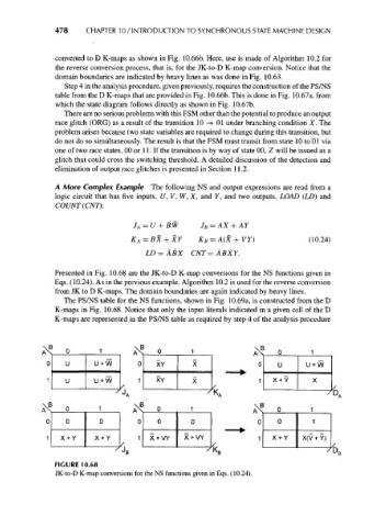
Presented in Fig. 10.68 are the JK-to-D K-map conversions for the NS functions given in
Eqs. (10.24). As in the previous example, Algorithm 10.2 is used for the reverse conversion
from JK to D K-maps. The domain boundaries are again indicated by heavy lines.
The PS/NS table for the NS functions, shown in Fig. 10.69a, is constructed from the D
K-maps in Fig. 10.68. Notice that only the input literals indicated in a given cell of the D
K-maps are represented in the PS/NS table as required by step 4 of the analysis procedure
\B
A
0 u + w 0 XY U + W
u + w XY X +Y
A\ B 0 . 1 . A" 6
X + Y X + Y X + VY X + VY X + Y X(V + Y)
D
B I XQ D C
FIGURE 10.68
JK-to-D K-map conversions for the NS functions given in Eqs. (10.24).