
Page 505 - Engineering Digital Design
P. 505
10.12 DESIGN OF SIMPLE SYNCHRONOUS STATE MACHINES 475
NS forming
logic | j— 1 r~^ [^-^ ^ ^— 1 Output
forming
CK(D—: qp—.—I qp-,—t 4—, T logic
Memory < A B U Jjj-j;
A^L;
A(H)
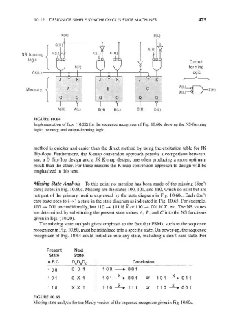
FIGURE 10.64
Implementation of Eqs. (10.22) for the sequence recognizer of Fig. 10.60c showing the NS-forming
logic, memory, and output-forming logic.
method is quicker and easier than the direct method by using the excitation table for JK
flip-flops. Furthermore, the K-map conversion approach permits a comparison between,
say, a D flip-flop design and a JK K-map design, one often producing a more optimum
result than the other. For these reasons the K-map conversion approach to design will be
emphasized in this text.
Missing-State Analysis To this point no mention has been made of the missing (don't
care) states in Fig. 10.60c. Missing are the states 100, 101, and 110, which do exist but are
not part of the primary routine expressed by the state diagram in Fig. 10.60c. Each don't
care state goes to (—>) a state in the state diagram as indicated in Fig. 10.65. For example,
100 -> 001 unconditionally, but 110 -> 111 if X or 110 -> 001 if X, etc. The NS values
are determined by substituting the present state values A, B, and C into the NS functions
given in Eqs. (10.20).
The missing state analysis gives emphasis to the fact that FSMs, such as the sequence
recognizer in Fig. 10.60, must be initialized into a specific state. On power-up, the sequence
recognizer of Fig. 10.64 could initialize into any state, including a don't care state. For
Present Next
State State
D D
AB C PA B C Conclusion
100 00 1 1 00 - > 001
101 0X 1 1 0 1 -^-* 001 or 101 -*-* 0 1 1
110 X X 1 1 1 0 --* 111 or 110 --* 0 0 1
FIGURE 10.65
Missing state analysis for the Mealy version of the sequence recognizer given in Fig. 10.60c.