
Page 507 - Engineering Digital Design
P. 507
CK(L)
A(H)
X X
X X
(b)
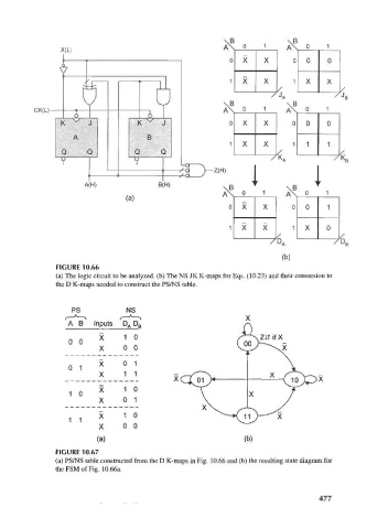
FIGURE 10.66
(a) The logic circuit to be analyzed, (b) The NS JK K-maps for Eqs. (10.23) and their conversion to
the D K-maps needed to construct the PS/NS table.
PS NS
A B Inputs D A D B
X 1 0
0 0
X 0 0
X 0 1
0 1
X 1 1
X 1 0
1 0
X 0 1
1 1 X 1 0
X 0 0
(a) (b)
FIGURE 10.67
(a) PS/NS table constructed from the D K-maps in Fig. 10.66 and (b) the resulting state diagram for
theFSMofFig. 10.66a.
477