
Page 502 - Engineering Digital Design
P. 502
472 CHAPTER 10 / INTRODUCTION TO SYNCHRONOUS STATE MACHINE DESIGN
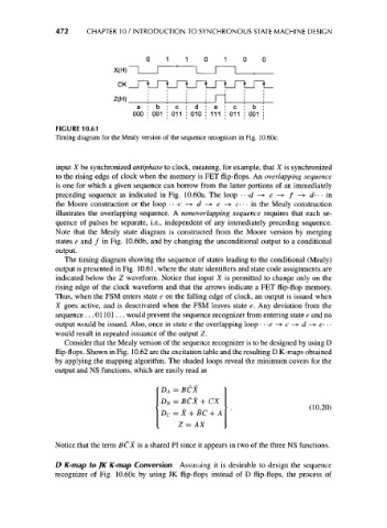
FIGURE 10.61
Timing diagram for the Mealy version of the sequence recognizer in Fig. 10.60c.
input X be synchronized antiphase to clock, meaning, for example, that X is synchronized
to the rising edge of clock when the memory is FET flip-flops. An overlapping sequence
is one for which a given sequence can borrow from the latter portions of an immediately
preceding sequence as indicated in Fig. 10.60a. The loop • • -d -» e —>• / -» d- • • in
the Moore construction or the loop • • -c -> d -» e -> c- • • in the Mealy construction
illustrates the overlapping sequence. A nonoverlapping sequence requires that each se-
quence of pulses be separate, i.e., independent of any immediately preceding sequence.
Note that the Mealy state diagram is constructed from the Moore version by merging
states e and / in Fig. 10.60b, and by changing the unconditional output to a conditional
output.
The timing diagram showing the sequence of states leading to the conditional (Mealy)
output is presented in Fig. 10.61, where the state identifiers and state code assignments are
indicated below the Z waveform. Notice that input X is permitted to change only on the
rising edge of the clock waveform and that the arrows indicate a FET flip-flop memory.
Thus, when the FSM enters state e on the falling edge of clock, an output is issued when
X goes active, and is deactivated when the FSM leaves state e. Any deviation from the
sequence ... 01101... would prevent the sequence recognizer from entering state e and no
output would be issued. Also, once in state e the overlapping loop • • -e -+ c -*• d -+ e- • •
would result in repeated issuance of the output Z.
Consider that the Mealy version of the sequence recognizer is to be designed by using D
flip-flops. Shown in Fig. 10.62 are the excitation table and the resulting D K-maps obtained
by applying the mapping algorithm. The shaded loops reveal the minimum covers for the
output and NS functions, which are easily read as
D A = BCX
D B = BCX + CX
(10.20)
D C = X + BC + A
Z = AX
Notice that the term BCX is a shared PI since it appears in two of the three NS functions.
D K-map to JK K-map Conversion Assuming it is desirable to design the sequence
recognizer of Fig. 10.60c by using JK flip-flops instead of D flip-flops, the process of