
Page 504 - Engineering Digital Design
P. 504
474 CHAPTER 10 / INTRODUCTION TO SYNCHRONOUS STATE MACHINE DESIGN
BC \BC \BC
00 01 11 10 A\ °° ° 1 11 10 A\ °° 01 1 1 1 0
0 0 0 X x
0 1
* * *
IV
,BC \BC / J A \BC /K A
00 01 11 10 A\ °° 01 11 10 A \ °° 01 11 1 0
0 X X X X
# X (*
*
,BC \BC \BC
00 01 11 10 A \ °° 01 11 10 A\ °° 01 11 10
X 1 X X
«• ^ 1 ^
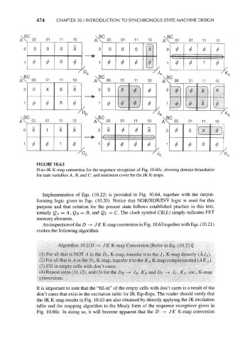
FIGURE 10.63
D-to-JK K-map conversion for the sequence recognizer of Fig. 10.60c, showing domain boundaries
for state variables A, B, and C, and minimum cover for the JK K-maps.
Implementation of Eqs. (10.22) is provided in Fig. 10.64, together with the output-
forming logic given in Eqs. (10.20). Notice that NOR/XOR/INV logic is used for this
purpose and that notation for the present state follows established practice in this text,
namely QA = A, QB = B, and Q c = C. The clock symbol CK(L) simply indicates FET
memory elements.
An inspection of the D -> JK K-map conversion in Fig. 10.63 together withEqs. (10.21)
evokes the following algorithm:
Algorithm 10.2:£> -» JK K-map Conversion [Refer to Eq. (10.21)]
(1) For all that is NOT A in the D A K-map, transfer it to the J A K-map directly (AJ A).
(2) For all that is A in the DA K-map, transfer it to the KA K-map complemented (A KA )•
(3) Fill in empty cells with don't cares.
(4) Repeat steps (1), (2), and (3) for the D B -» J B, K B and £> c -*• Jc, %c, etc., K-map
conversions.
It is important to note that the "fill-in" of the empty cells with don't cares is a result of the
don't cares that exist in the excitation table for JK flip-flops. The reader should verify that
the JK K-map results in Fig. 10.63 are also obtained by directly applying the JK excitation
table and the mapping algorithm to the Mealy form of the sequence recognizer given in
Fig. 10.60c. In doing so, it will become apparent that the D -+ JK K-map conversion