
Page 509 - Engineering Digital Design
P. 509
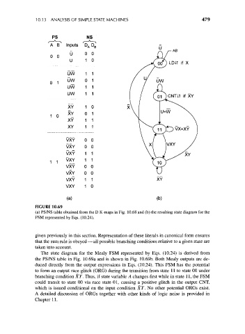
10.13 ANALYSIS OF SIMPLE STATE MACHINES                             479


                        PS             NS
                       A B    Inputs  D
                                      />i  B
                                U     0 0
                        0 0
                                U     1 0

                               UW     1 1
                               UW     0 1
                       0 1
                               UW     1 1
                               UW     1 1

                               XY     1 0
                               XY     0 1
                        1 0
                               XY     1 1
                               XY     1 1

                              VXY     0 0
                              VXY     0 0
                              VXY     1 1
                              VXY     1 1
                       1 1
                              VXY     0 0
                              VXY     0 0
                              VXY     1 1                          XY
                              VXY     1 0

                              (a)                                  (b)
                 FIGURE 10.69
                 (a) PS/NS table obtained from the D K-maps in Fig. 10.68 and (b) the resulting state diagram for the
                 FSM represented by Eqs. (10.24).


                 given previously in this section. Representation of these literals in canonical form ensures
                 that the sum rule is obeyed — all possible branching conditions relative to a given state are
                 taken into account.
                    The state diagram for the Mealy FSM represented by Eqs. (10.24) is derived from
                 the PS/NS table in Fig. 10.69a and is shown in Fig. 10.69b. Both Mealy outputs are de-
                 duced directly from the output expressions in Eqs. (10.24). This FSM has the potential
                 to form an output race glitch (ORG) during the transition from state 11 to state 00 under
                 branching condition XY. Thus, if state variable A changes first while in state 11, the FSM
                 could transit to state 00 via race state 01, causing a positive glitch in the output CNT,
                 which is issued conditional on the input condition XY. No other potential ORGs exist.
                 A detailed discussion of ORGs together with other kinds of logic noise is provided in
                 Chapter 11.