
Page 510 - Engineering Digital Design
P. 510
480 CHAPTER 10 / INTRODUCTION TO SYNCHRONOUS STATE MACHINE DESIGN
10.14 VHDL DESCRIPTION OF SIMPLE STATE MACHINES
An introduction to VHDL description of devices is given in Section 6.10. There, certain key
words are introduced in bold type and examples are given of the behavioral and structural
descriptions of combinational primitives. In Section 8.10, VHDL is used in the description of
a full adder to illustrate three levels of abstraction. In this section, the behavioral descriptions
of two FSMs (a flip-flop and a simple synchronous state machine) are presented by using
the IEEE standard package stdJogicJ164.
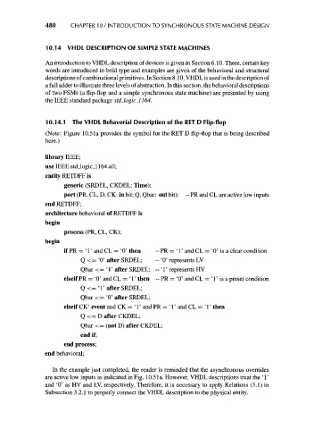
10.14.1 The VHDL Behavorial Description of the RET D Flip-flop
(Note: Figure 10.5la provides the symbol for the RET D flip-flop that is being described
here.)
library IEEE;
use IEEE.std_logic_l 164.all;
entity RETDFF is
generic (SRDEL, CKDEL: Time);
port (PR, CL, D, CK: in bit; Q, Qbar: out bit); ~ PR and CL are active low inputs
end RETDFF;
architecture behavioral of RETDFF is
begin
process (PR, CL, CK);
begin
if PR = ' 1' and CL = '0' then ~ PR = ' 1' and CL = '0' is a clear condition
Q <= '0' after SRDEL; - '0' represents LV
Qbar < = ' 1' after SRDEL; --' 1' represents HV
elseif PR = '0' and CL = ' 1' then - PR = '0' and CL = ' 1' is a preset condition
Q<= T after SRDEL;
Qbar <= '0' after SRDEL;
elseif CK' event and CK = ' 1' and PR = ' 1' and CL = ' 1' then
Q<= D after CKDEL;
Qbar <= (not D) after CKDEL;
end if;
end process;
end behavioral;
In the example just completed, the reader is reminded that the asynchronous overrides
are active low inputs as indicated in Fig. 10.5 la. However, VHDL descriptions treat the ' 1'
and '0' as HV and LV, respectively. Therefore, it is necessary to apply Relations (3.1) in
Subsection 3.2.1 to properly connect the VHDL description to the physical entity.