
Page 511 - Engineering Digital Design
P. 511
10.14 VHDL DESCRIPTION OF SIMPLE STATE MACHINES 481
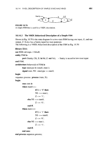
FIGURE 10.70
A simple FSM that is used for a VHDL description.
10.14.2 The VHDL Behavioral Description of a Simple FSM
Shown in Fig. 10.70 is the state diagram for a two-state FSM having one input, X, and one
output, Z. It also has a Sanity input for reset purposes.
The following is a VHDL behavioral description of the FSM in Fig. 10.70:
library IEEE;
use IEEE.std_logic_1164.all;
entity FSM is
port (Sanity, CK, X: in bit; Z: out bit); -- Sanity is an active low reset input
end FSM;
architecture behavorial of FSM is
type statelype is (stateO, statel);
signal state, NS : statetype := stateO;
begin
sequence_process: process (state, X);
begin
case state is
when stateO =>
ifX= 'O'then
NS <= statel;
Z <='!';
elseNS <= stateO;
Z<= '0';
end if;
when statel—>
ifX= T then
NS <= stateO;
Z <= '0';
elseNS <= statel;
Z<= '!';
end if;
end case;
end process sequence_process;