
Page 587 - Engineering Digital Design
P. 587
PROBLEMS 557
X+Y
FIGURE P11.6
(c) From the results of parts (a) and (b), analyze this FSM by constructing the
revised state diagram. To do this, follow the examples in Section 10.13. Are
ORGs now possible? Are they possible in the state diagram of Fig. PI 1.6?
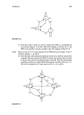
11.14 Shown in Fig. PI 1.7 is a state diagram for an FSM that has two inputs, X and Y,
and three outputs, P, Q, and R.
(a) Given the state code assignment indicated, use the array algebraic approach to
obtain the NS expressions for this FSM. To do this, first construct the state table
to obtain state matrix S and the destination matrix D. Then find the function
matrix FNS and the next matrix NS by following the example in Section 11.11.
End with an optimum set of logic equations for DA, DB, and DC-
XY
XY
N. V-^CUT
^*s^ S r* ^ ^>
XY
FIGURE P11.7