
Page 588 - Engineering Digital Design
P. 588
558 CHAPTER 11 / SYNCHRONOUS FSM DESIGN CONSIDERATIONS
(b) Repeat the algebraic approach to obtain the output functions for P, Q, and R.
Are static 1-hazards present? If so, indicate whether they are internally ini-
tiated or externally initiated, and give the hazard cover required to eliminate
them.
(c) From the results of parts (a) and (b), analyze this FSM by constructing the
revised state diagram. To do this, follow the examples in Section 10.13. Are
ORGs possible? Are they possible in the original state diagram of Fig. PI 1.7?
(d) Noticing that none of the principal states are used as race states, obtain each
output function in terms of the three variables of the state in which the output is
issued. Now comment on the presence or absence of ORGs and static hazards.
Is this a valid set of output function expressions and, if so, is this a special
case? Which is best, the results of (b) or those of (d)?
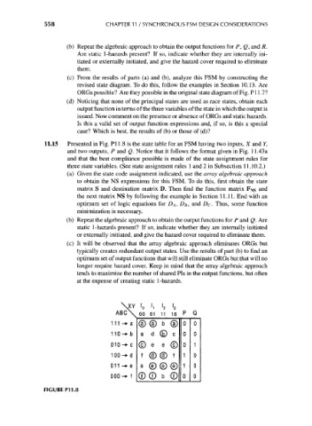
11.15 Presented in Fig. PI 1.8 is the state table for an FSM having two inputs, X and Y,
and two outputs, P and Q. Notice that it follows the format given in Fig. 11.43a
and that the best compliance possible is made of the state assignment rules for
three state variables. (See state assignment rules 1 and 2 in Subsection 11.10.2.)
(a) Given the state code assignment indicated, use the array algebraic approach
to obtain the NS expressions for this FSM. To do this, first obtain the state
matrix S and destination matrix D. Then find the function matrix F Ns and
the next matrix NS by following the example in Section 11.11. End with an
optimum set of logic equations for D A, D B, and D c. Thus, some function
minimization is necessary.
(b) Repeat the algebraic approach to obtain the output functions for P and Q. Are
static 1-hazards present? If so, indicate whether they are internally initiated
or externally initiated, and give the hazard cover required to eliminate them.
(c) It will be observed that the array algebraic approach eliminates ORGs but
typically creates redundant output states. Use the results of part (b) to find an
optimum set of output functions that will still eliminate ORGs but that will no
longer require hazard cover. Keep in mind that the array algebraic approach
tends to maximize the number of shared Pis in the output functions, but often
at the expense of creating static 1-hazards.
\XY I 0 \, I 3 I 2
ABC\ 00 01 11 10
111 -*i © © b @
a d © c
010-^c © e e @
100-^d
011 -*e a (e) (e) (i;
000-^ f 2) CD b CD
FIGURE P11.8