
Page 589 - Engineering Digital Design
P. 589
PROBLEMS 559
Start
PSCRYiT
8^80= 1,UT
8^80 = 0,UT
CNTiT
CMPUT
FINlTifCNT=8
CNT=8
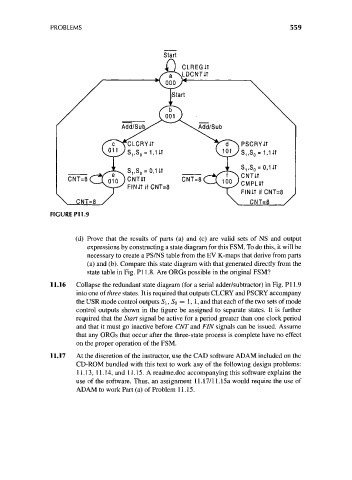
FIGURE P11.9
(d) Prove that the results of parts (a) and (c) are valid sets of NS and output
expressions by constructing a state diagram for this FSM. To do this, it will be
necessary to create a PS/NS table from the EV K-maps that derive from parts
(a) and (b). Compare this state diagram with that generated directly from the
state table in Fig. PI 1.8. Are ORGs possible in the original FSM?
11.16 Collapse the redundant state diagram (for a serial adder/subtractor) in Fig. PI 1.9
into one of three states. It is required that outputs CLCRY and PSCRY accompany
the USR mode control outputs S\, SQ = 1, 1, and that each of the two sets of mode
control outputs shown in the figure be assigned to separate states. It is further
required that the Start signal be active for a period greater than one clock period
and that it must go inactive before CNT and FIN signals can be issued. Assume
that any ORGs that occur after the three-state process is complete have no effect
on the proper operation of the FSM.
11.17 At the discretion of the instructor, use the CAD software ADAM included on the
CD-ROM bundled with this text to work any of the following design problems:
11.13, 11.14, and 11.15. A readme.doc accompanying this software explains the
use of the software. Thus, an assignment 11.17/11.15a would require the use of
ADAM to work Part (a) of Problem 11.15.