
Page 736 - Engineering Digital Design
P. 736
702 CHAPTER 14/ASYNCHRONOUS STATE MACHINE DESIGN AND ANALYSIS
(b)
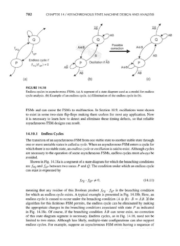
FIGURE 14.18
Endless cycles in asynchronous FSMs. (a) A segment of a state diagram used as a model for endless
cycle analysis, (b) Example of an endless cycle, (c) Elimination of the endless cycle in (b).
FSMs and can cause the FSMs to malfunction. In Section 10.9, oscillations were shown
to exist in some two-state flip-flops making them useless for most any application. Now
it is necessary to learn how to detect and eliminate these timing defects, so that reliable
asynchronous FSM designs can result.
14.10.1 Endless Cycles
The transition of an asynchronous FSM from one stable state to another stable state through
one or more unstable states is called a cycle. When an asynchronous FSM enters a cycle for
which there is no stable state, an endless cycle or oscillation is said to exist. Although cycles
are necessary to the operation of some asynchronous FSMs, endless cycles must always be
avoided.
Shown in Fig. 14.18a is a segment of a state diagram for which the branching conditions
are f PQ and /Q P between two states P and Q. The condition under which an endless cycle
can exist is expressed by
fpQ'for*U , (14.11)
meaning that any residue of this Boolean product /PQ • /QP is the branching condition
for which an endless cycle exists. A typical example is presented in Fig. 14.18b. Here, an
endless cycle is caused to occur under the branching condition (A © B) • B = AB. If the
algorithm for this fictitious FSM permits, the endless cycle can be eliminated by making
the appropriate changes in the branching conditions associated with state P as indicated
in Fig. 14.18c. Of course, if the branching condition A B can never exist, no correction
of this state diagram segment is necessary. Endless cycles, as in Fig. 14.18, need not be
limited to two states. Although less likely, multiple-state configurations can also support
endless cycles. For example, suppose an asynchronous FSM exists having a sequence of