
Page 231 - gas transport in porous media
P. 231
Chapter 13: Lattice Boltzmann Method
L=12 227
L=12
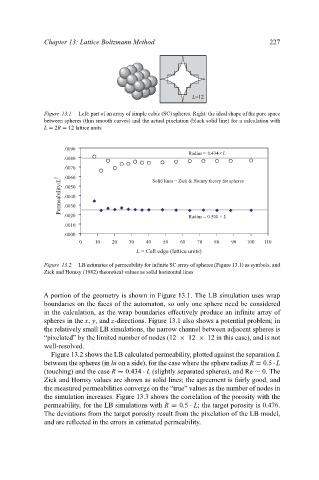
Figure 13.1. Left: part of an array of simple cubic (SC) spheres. Right: the ideal shape of the pore space
between spheres (thin smooth curves) and the actual pixelation (black solid line) for a calculation with
L = 2R = 12 lattice units
.0090
Radius= 0.434× L
.0080
.0070
.0060 Solid lines = Zick & Homsy theory for spheres
Permeability/L 2 .0050
.0040
.0030
.0020 Radius = 0.500 × L
.0010
.0000
0 10 20 30 40 50 60 70 80 90 100 110
L = Cell edge (lattice units)
Figure 13.2. LB estimates of permeability for infinite SC array of spheres (Figure 13.1) as symbols, and
Zick and Homsy (1982) theoretical values as solid horizontal lines
A portion of the geometry is shown in Figure 13.1. The LB simulation uses wrap
boundaries on the faces of the automaton, so only one sphere need be considered
in the calculation, as the wrap boundaries effectively produce an infinite array of
spheres in the x, y, and z-directions. Figure 13.1 also shows a potential problem; in
the relatively small LB simulations, the narrow channel between adjacent spheres is
“pixelated” by the limited number of nodes (12 × 12 × 12 in this case), and is not
well-resolved.
Figure 13.2 shows the LB calculated permeability, plotted against the separation L
between the spheres (in lu on a side), for the case where the sphere radius R = 0.5 · L
(touching) and the case R = 0.434 · L (slightly separated spheres), and Re ∼ 0. The
Zick and Homsy values are shown as solid lines; the agreement is fairly good, and
the measured permeabilities converge on the “true” values as the number of nodes in
the simulation increases. Figure 13.3 shows the correlation of the porosity with the
permeability, for the LB simulations with R = 0.5 · L; the target porosity is 0.476.
The deviations from the target porosity result from the pixelation of the LB model,
and are reflected in the errors in estimated permeability.