
Page 403 - High Power Laser Handbook
P. 403
372 So l i d - S t at e La s e r s The National Ignition Facility Laser 373
Failsafe SBS
FS AMP
grating fail safe
Pulser
10 mW 0.5 nJ/100 ns 100 nJ 10 nJ 2.5 nJ 1.3 nJ/30 ns 22 nJ
AO Phase FM-to-AM Optical
Oscillator AMP-A AMP-B AMP-C
modulator modulaor comp gate
400 mW
40 nJ 675 nJ 135 nJ peak power
AMC
370 nJ 58 nJ 12 nJ 200 nJ
AMP-E 1 × 4 AMP-F
AMP-D Disp comp 1 × 4
1 × 4
48 outputs
AMP-E 1 × 4 to main
laser system
AMP-E 1 × 4
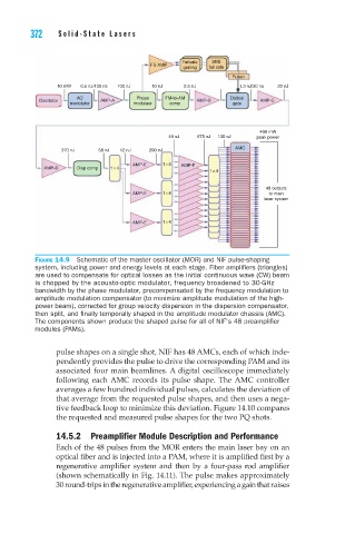
Figure 14.9 Schematic of the master oscillator (MOR) and NIF pulse-shaping
system, including power and energy levels at each stage. Fiber amplifiers (triangles)
are used to compensate for optical losses as the initial continuous wave (CW) beam
is chopped by the acousto-optic modulator, frequency broadened to 30-GHz
bandwidth by the phase modulator, precompensated by the frequency modulation to
amplitude modulation compensator (to minimize amplitude modulation of the high-
power beam), corrected for group velocity dispersion in the dispersion compensator,
then split, and finally temporally shaped in the amplitude modulator chassis (AMC).
The components shown produce the shaped pulse for all of NIF’s 48 preamplifier
modules (PAMs).
pulse shapes on a single shot, NIF has 48 AMCs, each of which inde-
pendently provides the pulse to drive the corresponding PAM and its
associated four main beamlines. A digital oscilloscope immediately
following each AMC records its pulse shape. The AMC controller
averages a few hundred individual pulses, calculates the deviation of
that average from the requested pulse shapes, and then uses a nega-
tive feedback loop to minimize this deviation. Figure 14.10 compares
the requested and measured pulse shapes for the two PQ shots.
14.5.2 Preamplifier Module Description and Performance
Each of the 48 pulses from the MOR enters the main laser bay on an
optical fiber and is injected into a PAM, where it is amplified first by a
regenerative amplifier system and then by a four-pass rod amplifier
(shown schematically in Fig. 14.11). The pulse makes approximately
30 round-trips in the regenerative amplifier, experiencing a gain that raises