Page 404 - High Power Laser Handbook
P. 404

372   So l i d - S t at e   La s e r s     The National Ignition Facility Laser    373


                    200                                                    20
                    180       Request                                      18
                    160       10 × Request                                 16
                              1st PQ
                    140                                                    14
                              10 × 1st PQ                                  12
                  Power (mW)  100  2nd PQ                                  10  Power × 10 (mW)
                    120
                              10 × 2nd PQ
                                                                           8
                    80
                    60                                                     6
                    40                                                     4
                           Power × 10
                    20                                                     2
                     0                                                     0
                      0          5         10        15         20        25
                                              Time (ns)
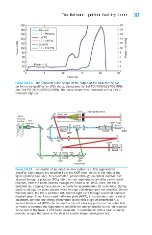
                 Figure 14.10  The temporal pulse shape at the output of the MOR for the two
                 performance qualification (PQ) shots, designated as 1st PQ (N060329-002-999)
                 and 2nd PQ (N060329-003-999). The pulse shape was measured with a 1-GHz
                 transient digitizer.


                                                    Lens  Diode pump arrays
                                        5-mm rod
                  Beam-                       Hollow duct
                  shaping
                  module  20X
                      expander                                        HWP  Fiber
                                                   POL                   launch
                                          Rotator                Isolator    MOR
                                              HWP

                                        POL
                                                                    QWP
                                                                       PC1
                                      POL      POL
                                           PC2
                                        HWP        HWP
                                                  (motorized)
                 Figure 14.11  Schematic of an injection laser system’s (ILS’s) regenerative
                 amplifier. Light enters the amplifier from the MOR fiber launch at the right of the
                 figure (dashed blue line). It is collimated, passed through an optical isolator, and
                 injected through a polarizer (POL) into the main regenerative amplifier cavity (solid
                 red line). After the beam passes through the Pockels cell (PC1) once, the PC is
                 switched on, trapping the pulse in the cavity for approximately 30 round-trips. During
                 each round-trip, the pulse passes twice through a diode-pumped rod amplifier. Before
                 the final pass, the PC is switched off, and the light exits through a second polarizer
                 (dashed green line). A motorized half-wave plate (HWP), in combination with a set of
                 polarizers, controls the energy transmitted to the next stage of amplification. A
                 second Pockels cell (PC2) can be used to clip off a trailing portion of the pulse that
                 is meant to saturate the regenerative amplifier for energy stability but is not required
                 in the rest of the laser. A 20X beam expander, in combination with a beam-shaping
                 module, sculpts the beam to the desired spatial shape (solid green line).
   399   400   401   402   403   404   405   406   407   408   409