
Page 405 - High Power Laser Handbook
P. 405
374 So l i d - S t at e La s e r s The National Ignition Facility Laser 375
Fluence (J/cm 2 ) 1.0
0.8
0.6
0.4
0.2
0.0
1.0
0.0
y (cm) 0.5 1.0
−1.0 −0.5 0.0
−1.0 x (cm)
(a) (b) (c)
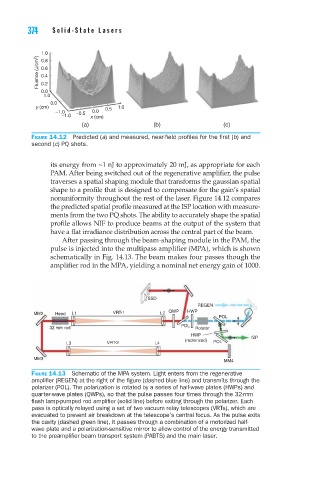
Figure 14.12 Predicted (a) and measured, near-field profiles for the first (b) and
second (c) PQ shots.
its energy from ~1 nJ to approximately 20 mJ, as appropriate for each
PAM. After being switched out of the regenerative amplifier, the pulse
traverses a spatial shaping module that transforms the gaussian spatial
shape to a profile that is designed to compensate for the gain’s spatial
nonuniformity throughout the rest of the laser. Figure 14.12 compares
the predicted spatial profile measured at the ISP location with measure-
ments from the two PQ shots. The ability to accurately shape the spatial
profile allows NIF to produce beams at the output of the system that
have a flat irradiance distribution across the central part of the beam.
After passing through the beam-shaping module in the PAM, the
pulse is injected into the multipass amplifier (MPA), which is shown
schematically in Fig. 14.13. The beam makes four passes though the
amplifier rod in the MPA, yielding a nominal net energy gain of 1000.
SSD
REGEN
MM2 Head L1 VRT-1 L2 QWP HWP
POL
32 mm rod POL Rotator
HWP ISP
(motorized)
L3 VRT-2 L4 POL
MM3
MM4
Figure 14.13 Schematic of the MPA system. Light enters from the regenerative
amplifier (REGEN) at the right of the figure (dashed blue line) and transmits through the
polarizer (POL). The polarization is rotated by a series of half-wave plates (HWPs) and
quarter-wave plates (QWPs), so that the pulse passes four times through the 32-mm
flash lamp-pumped rod amplifier (solid line) before exiting through the polarizer. Each
pass is optically relayed using a set of two vacuum relay telescopes (VRTs), which are
evacuated to prevent air breakdown at the telescope’s central focus. As the pulse exits
the cavity (dashed green line), it passes through a combination of a motorized half-
wave plate and a polarization-sensitive mirror to allow control of the energy transmitted
to the preamplifier beam transport system (PABTS) and the main laser.