
Page 410 - High Power Laser Handbook
P. 410
378 So l i d - S t at e La s e r s The National Ignition Facility Laser 379
o
c
E
e 2ω
E 3ω
E 1ω
e
c
Type II THG
+ k = k
k 1e 2o 3e
dKDP
E 1ω o
Type I SHG
+ k = k
k 1o 1o 2e
KDP
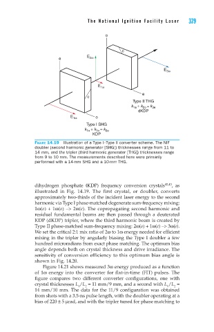
Figure 14.19 Illustration of a Type I–Type II converter scheme. The NIF
doubler (second harmonic generator [SHG]) thicknesses range from 11 to
14 mm, and the tripler (third harmonic generator [THG]) thicknesses range
from 9 to 10 mm. The measurements described here were primarily
performed with a 14-mm SHG and a 10-mm THG.
dihydrogen phosphate (KDP) frequency conversion crystals 42,43 , as
illustrated in Fig. 14.19. The first crystal, or doubler, converts
approximately two-thirds of the incident laser energy to the second
harmonic via Type I phase-matched degenerate sum-frequency mixing:
1ω(o) + 1ω(o) −> 2ω(e). The copropagating second harmonic and
residual fundamental beams are then passed through a deuterated
KDP (dKDP) tripler, where the third harmonic beam is created by
Type II phase-matched sum-frequency mixing: 2ω(o) + 1ω(e) −> 3ω(e).
We set the critical 2:1 mix ratio of 2ω to 1ω energy needed for efficient
mixing in the tripler by angularly biasing the Type I doubler a few
hundred microradians from exact phase matching. The optimum bias
angle depends both on crystal thickness and drive irradiance. The
sensitivity of conversion efficiency to this optimum bias angle is
shown in Fig. 14.20.
Figure 14.21 shows measured 3ω energy produced as a function
of 1ω energy into the converter for flat-in-time (FIT) pulses. The
figure compares two different converter configurations, one with
crystal thicknesses L /L = 11 mm/9 mm, and a second with L /L =
2
1
2
1
14 mm/10 mm. The data for the 11/9 configuration was obtained
from shots with a 3.5-ns pulse length, with the doubler operating at a
bias of 220 ± 5 μrad, and with the tripler tuned for phase matching to