
Page 411 - High Power Laser Handbook
P. 411
380 So l i d - S t at e La s e r s The National Ignition Facility Laser 381
13 11 mm
L 1 = 14 12
100
Bandwidth about optimum (µrad int)* 0
50
−50
< 3%
*∆η 3
−100
0 1 2 3 4 5
2
(GW/cm )
I 1
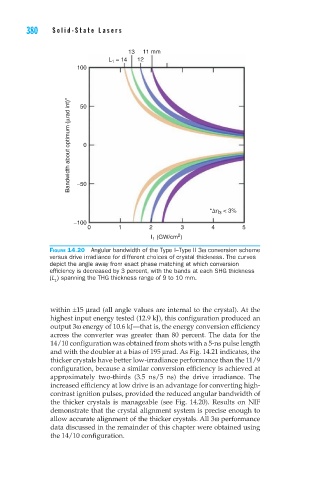
Figure 14.20 Angular bandwidth of the Type I–Type II 3ω conversion scheme
versus drive irradiance for different choices of crystal thickness. The curves
depict the angle away from exact phase matching at which conversion
efficiency is decreased by 3 percent, with the bands at each SHG thickness
(L ) spanning the THG thickness range of 9 to 10 mm.
1
within ±15 μrad (all angle values are internal to the crystal). At the
highest input energy tested (12.9 kJ), this configuration produced an
output 3ω energy of 10.6 kJ—that is, the energy conversion efficiency
across the converter was greater than 80 percent. The data for the
14/10 configuration was obtained from shots with a 5-ns pulse length
and with the doubler at a bias of 195 μrad. As Fig. 14.21 indicates, the
thicker crystals have better low-irradiance performance than the 11/9
configuration, because a similar conversion efficiency is achieved at
approximately two-thirds (3.5 ns/5 ns) the drive irradiance. The
increased efficiency at low drive is an advantage for converting high-
contrast ignition pulses, provided the reduced angular bandwidth of
the thicker crystals is manageable (see Fig. 14.20). Results on NIF
demonstrate that the crystal alignment system is precise enough to
allow accurate alignment of the thicker crystals. All 3ω performance
data discussed in the remainder of this chapter were obtained using
the 14/10 configuration.