
Page 149 - How To Implement Lean Manufacturing
P. 149
How to Do Lean—The Four Strategies to Becoming Lean 127
Appendix D—The Spaghetti Diagram
Background
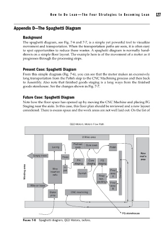
The spaghetti diagram, see Fig. 7-6 and 7-7, is a simple yet powerful tool to visualize
movement and transportation. When the transportation paths are seen, it is often easy
to spot opportunities to reduce these wastes. A spaghetti diagram is normally hand-
drawn on a simple floor layout. The example here is of the movement of a motor as it
progresses through the processing steps.
Present Case: Spaghetti Diagram
From this simple diagram (Fig. 7-6), you can see that the motor makes an excessively
long transportation from the Polish step to the CNC Machining process and then back
to Assembly. Also note that finished goods staging is a long ways from the finished
goods storehouse. See the changes shown in Fig. 7-7.
Future Case: Spaghetti Diagram
Note how the floor space has opened up by moving the CNC Machine and placing FG
Staging near the aisle. In this case, this floor plan should be reviewed and a new layout
considered. There is excess space and the work areas are not well laid out. On the list of
QED Motors, Motors Flow Path
Utilities area
Preheat
Cure oven
Lacing oven Polish
Raw
Empty trees mat’s
Press
area
PH Cure FG
staging staging staging
Winding area insertion pot Varnish Final Final Conveyor
Hi
Wire
assy
cells
A
test,
packing Final
Wire on trees assy
B
Stator CNC machining
prep
FG storehouse
FIGURE 7-6 Spaghetti diagram, QED Motors, before.