
Page 586 - Instrumentation Reference Book 3E
P. 586
568 Non-destructive testing
(b)
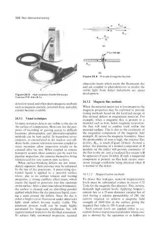
Figure 24.6 Principleof magneticflux test
ultraviolet lasers which excite the fluorescent dye
and are coupled to photodetectors to receive the
visible light from defect indications are under
development.
Figure 24.5 High-resolution flexible fiberscope.
Courtesy P.W. Allen & Co.
24.3.2 Magnetic flux methods
detection visual and other electromagnetic methods
such as magnetic particle, potential drop, and eddy When the material under test is ferromagnetic the
current become available. magnetic properties may be exploited to provide
testing methods based on the localized escape of
flux around defects in magnetized material. For
24.3.1 Visual techniques example, when a magnetic flux is present in a
In many instances defects are visible to the eye on material such as iron, below magnetic saturation,
the surface of components. However, for the pur- the flux will tend to confine itself within the
poses of recording or gaining access to difficult material surface. This is due to the continuity of
locations, photographic and photomicrographic the tangential component of the magnetic field
methods can be very useful. In hazardous envir- strength, H, across the magnetic boundary. Since
onments, as encountered in the nuclear and off- the permeability of iron is high, the external flux
shore fields, remote television cameras coupled to density, BeXt, is small (Figure 24.6(a)). Around a
video recorders allow inspection results to be defect, the presence of a normal component of B
assessed after the test. When coupled to remote incident on the defect will provide continuity of
transport systems these cameras can be used for the flux to the air, and a localized flux escape will
pipeline inspection, the cameras themselves being be apparent (Figure 24.6(b)). If only a tangential
miniaturized for very narrow pipe sections. component is present, no flux leak occurs, max-
When surface-breaking defects are not imme- imum leakage conditions being obtained when B
diately apparent. their presence may be enhanced is normal to the defect.
by the use of dye penetrants. A penetrating dye-
loaded liquid is applied to a material surface 24.3.2.1 Magnetization methods
where, due to its surface tension and wetting
properties, a strong capillary effect exists, which To detect flux leakages, material magnetization
causes the liquid to penetrate into fine openings levels must be substantial (values in excess 0.72
on the surface. After a short time (about 10 minutes), Tesla for the magnetic flux density). This. in turn,
the surface is cleaned and an absorbing powder demands high current levels. Applying Ampere's
applied which blots the dye penetrant liquid, caus- current law to a 25-mm diameter circular bar of
ing a stain around the defects. Since the dye is steel having a relative permeability of 240, the
either a bright red or fluorescent under ultraviolet current required to achieve a magnetic field
light, small defects become readily visible. The strength of 2400Nm at the surface giving the
penetrant process itself can be made highly required flux value is 188 A peak current.
automated for large-scale production, but still Such current levels are applied either as a.c.
requires trained inspectors for the final assessment. current from a step-down transformer whose out-
To achieve fully automated inspection, scanned put is shorted by the specimen or as halfwave