
Page 591 - Instrumentation Reference Book 3E
P. 591
Ultrasonics 573
Ultrasonic waves are generated in a transducer skip distance may be used. This is the distance
mounted on a probe. The transducer material has measured over the surface of the body between
the property of expanding and contracting under the probe index or beam exit point for the probe
an alternating electrical field due to the piezo- and the point where the beam axis impinges on
electiric effect. It can thus transform electrical the surface after following a double traverse path.
oscilllations into mechanical vibrations and vice Accurate defect location is possible using the skip
versa. Since the probe is outside the specimen to distance and the beam path length (Figures
be tested, it is necessary to provide a coupling 24.14(b) and (c)).
agent between probe and specimen. The coup- A condition of resonance exists when the thick-
lant, a liquid or pliable solid, is interposed ness of a component is exactly equal to half the
between probe surface and specimen surface, wavelength of the incident ultrasonic energy, Le.
and assists in the passage of ultrasonic energy. the component will vibrate with its natural fre-
The probe may be used to transmit energy as a quency. The condition causes an increase in the
transmitter, receive energy as a receiver, or trans- amplitude of the received pulse which can readily
mit and receive as a transceiver. A characteristic be identified. The condition of resonance can also
of the transceiver or single-crystal probe is the be obtained if the thickness is a multiple of the
dead zone, where defects cannot be resolved with half-wavelength. The resonance method conse-
any accuracy due to the transmission-echo width. quently involves varying the frequency of uitra-
Information on the passage of ultrasonic energy sonic waves to excite a maximum amplitude of
in the specimen under test is provided by way of vibration in a body or part of a body, generally
the Ixansducer, in the form of electrical impulses for the purpose of determining thickness from
which are displayed on a cathode ray tube screen. one side only.
The most commonly used presentation of the
info rrnation is A-scan, where the horizontal base 24.4.2 The ultrasonic test equipment controls and
line represents distance or time intervals and the visual presentation
vertical axis gives signal amplitude or intensities
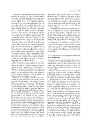
of transmitted or reflected signals. In most ultrasonic sets, the signal is displayed on
The basic methods of examination are trans- a cathode ray tube (CRT). Operation of the
miss;ion; pulse-echo, and resonance. In the trans- instrument is similar in both the through trans-
mission method an ultrasonic beam of energy is mission and pulse-echo techniques, and block dia-
pase:ed through a specimen and investigated by grams of the test equipment are shown in Figures
placing an ultrasonic transmitter on one face and 24.15(a) and (b).
a receiver on the other. The presence of internal The master timer controls the rate of gener-
flaws is indicated by a reduction in the amplitude ation of the pulses or pulse repetition frequency
of the received signal or a loss of signal. No (PRF) and supplies the timebase circuit giving
indication of defect depth is provided. the base line whilst the pulse generator ccntrols
Although it is possible with the pulse echo the output of the pulses or pulse energy which
method to use separate probes it is more common is transmitted to the probe. At the probe, elec-
to have the transmitter and receiver housed trical pulses are converted via the transducer
within the one probe, a transceiver. Hence access into mechanical vibrations at the chosen fre-
to one surface only is necessary. This method quency and directed into the test material. The
relies on energy reflected from within the mater- amount of energy passing into the specimen is
ial, finding its way back to the probe. Informa- very small. On the sound beam returning to the
tion is provided on the time taken by the pulse to probe, the mechanical vibrations are recon-
travel from the transmitter to an obstacle, back- verted at the transducer into electrical oscilla-
wall, or flaw and return to the receiver. Time is tions. This is known as the piezoelectric effect.
proportional to the distance of the ultrasonic In the main, transmitter and receiver probes are
beam path, hence the cathode ray tube may be combined. At the CRT the timebase amplifier
calibrated to enable accurate thickness measure- controls the rate of sweep of the beam across
ment or defect location to be obtained (Figure the fact of the tube which, by virtue of the
24:14(a)). For a defect suitably orientated to the relationship b'etween the distance travelled by
beam direction an assessment of defect size can be ultrasonic waves in unit time, i.e., velocity, can
made from the amplitude of the reflected signal. be used as a distance depth scale when locating
Compression probes are used in this test method defects or measuring thickness. Signals coming
to transmit compressional waves into the material from the receiver probe to the signal amplifier
normal to the entry surface. On the other hand, are magnified, this working in conjunction with
shear probes are used to transmit shear waves an incorporated attenuator control. The signal
where it is desirable to introduce the energy into is produced in the vertical axis. Visual display
the material at an angle, and a reference called the is by CRT with the transmitted and received