
Page 592 - Instrumentation Reference Book 3E
P. 592
574 Non-destructive testing
Y CRT display
Backwall
echo
Height
of echo
Defect
Test
piece I
I -
I - Distance * X
a-
/\ (a) I 4 b
CRT display
No defect
s
Probe
y
t
d
i
Height CRT display
of echo
0 = probe angle
I
Distance X
yI CRT display
Distance X
LBeam path length4
(C)
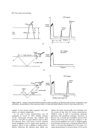
Figure 24.14 Displays presented by different ultrasonic probes and defects. (a) Distance (time) of travel-compression-wave
examination; (b) skip distance-shear-wave examination; (c) beam path length (distance of travel)-shear-wave examination.
signals in their proper time sequence with indi- deflect the beam horizontally and vertically over
cations of relative amplitude. the screen of the tube. In A-scan presentation,
A-, B- and C-scan presentations can be deflector plate X and Y coordinates represent
explained in terms of CRT display (Figure timebase and amplified response. However, in
24.16). Interposed between the cathode and B-scan the received and amplified echoes from
anode in the CRT is a grid which is used to limit defects and from front and rear surfaces of the
the electron flow and hence control ultimate test plate are applied, not to the Y deflector plate
screen brightness as it is made more positive or as in normal A-scan, but to the grid of the CRT in
negative. There is also a deflector system imme- order to increase the brightness of the trace. If a
diately following the electron gun which can signal proportional to the movement of the probe