
Page 587 - Instrumentation Reference Book 3E
P. 587
Surface-inspection methods 569
------ -- -
< I
0 (JB
Current flow r
/
Coil
Threading bar
I
Electromagnet
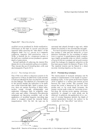
Figure! 24.7 Waysof inducing flux
rectified current produced by diode rectification. unwound and played through a tape unit, which
Differ1:nces in the type of current used become detects the presence of the recorded flux leakages.
apparent when assessing the “skin depth” of the For more dynamic situations, such as in the on-
magnetic field. For a.c. current in a magnetic line testing of tube and bar materials, a faster
conductor, magnetic field penetration, even at detection technique for the recording of indica-
50Hz. is limited; the d.c. component present in tions is required. A small detector head, compris-
the half-wave rectified current produces a greater ing a highly permeable yoke on which a number
depth of penetration. of turns of wire are wrapped, can be used to detect
Sev’eral methods of achieving the desired flux small flux leakages by magnetic induction as the
density levels at the material surface are available. flux leak passes under the detector (Figure 24.8).
They include the use of threading bars, coils, and The material motion can be linked to a chart
electromagnets (Figure 24.7). recorder showing impulses as they occur.
24.3.2.2 Flux-leakage detection 24.3.3 Potential drop techniques
One of the most effective detection systems is the The measurement of material resistance can be
application of finely divided ferric-oxide particles related to measurements of the depth of surface-
to form an indication by their accumulation around breaking cracks. A four-point probe head (Figure
the flux leakage. The addition of a fluorescent dye 24.9) is applied to a surface and current passed
to the particle enables the indication to be easily between the outer probes. The potentiai drop
seen under ultraviolet light. Such a system, how- across the crack is measured by the two inner
ever, does not sustain recording of defect infor- probes and, as the crack depth increases. the
mation except through photographic and greater current path causes an increasing poten-
replication techniques such as strippable mag- tial drop. By varying probe spacing, maximum
netic paint and rubber. Alternative flux-detection sensitivity to changes in crack depth can be
techniques are becoming available, such as the obtained. In addition, the application of a.c. CUI-
application of modified magnetic recording tape rent of varying frequency permits the depth of
which is wrapped around the material before current penetration beneath the surface to be
magnetization. After the test, the tape can be varied due to the “skin effect” (see below).
Laminated
core
-+-A 1-*
m- v -velocity
Figure 24.8 Detection of flux leakage. A/. flux-leakage widlh; A$: flux-leakage magnltude; V induced voltage