
Page 589 - Instrumentation Reference Book 3E
P. 589
Surface-inspection methods 571
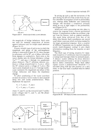
In setting up such a unit the movement of the
spot during the lift-off of the probe from the sur-
face identifies the magnetic circuit or permeability
axis, whereas defect deflection and conductivity
changes will introduce a component primarily
along an axis at riglit angles to the permeability
axis (Figure 24.13).
Additional vector processing can take place to
remove the response from a known geometrical
Te'st coil 1 feature. Compensation probes can produce a sig-
Figure 24.17 Simple type of eddy-current detector. nal from the feature, such as support members,
this signal being subtracted from that of the
defect plus feature. Such cancellation can record
the magnitude of bridge imbalance. Such units small defect responses which are being masked by
are used for material comparison of known the larger geometrical response. Also, a number
against unknown and for simple crack detection of different frequencies can be applied simultan-
(Figure 24.11). eously (multi-frequency testing) to give depth
A imore versatile type of unit is one in which the information resulting from the response at each
magnitude and phase of the coil-impedance frequency.
change is measured (Figure 24.12), since changes The third type of testing situation for large-
in inductance will be 90" out of phase with those scale inspection of continuous material comprises
from changes in conductivity. Such units as the a testing head through which the material passes.
vector display take the bridge imbalance voltage A detector system utilizing the phase detection
Voei(w'+d), and pass it through two quadrature units discussed previously is set up to respond to
phas'e detectors. The 0" reference detector pro- known defect orientations. When these defect
duces a voltage proportional to Vo cos @, whilst signals exceed a predetermined threshold it is
the 90" detector gives a voltage of Vo sin 4. The recorded along with the tube position on a strip
vector point displayed on an X-Ystorage oscillo- chart, or the tube itself is marked with the defect
scope represents the magnitude and phase of the position.
voltaige imbalance and hence the impedance
change.
To allow positioning of the vector anywhere
around the screen a vector rotator is incorporated
using sine and cosine potentiometers. These
implement the equation
V.. = V,cos@ - V,sind
y, = V, sin 4 + V, cos 4
where VL and Vl are the rotated X and Y oscillo-
scope voltages and V, and V, are the phase-
detector outputs. Figure 24.13 CRTdisplay for eddy-current detection.
oscilloscope
Figure 24.12 Eddy-current detection with phase discrimination.