
Page 593 - Instrumentation Reference Book 3E
P. 593
Ultrasonics 575
(b)
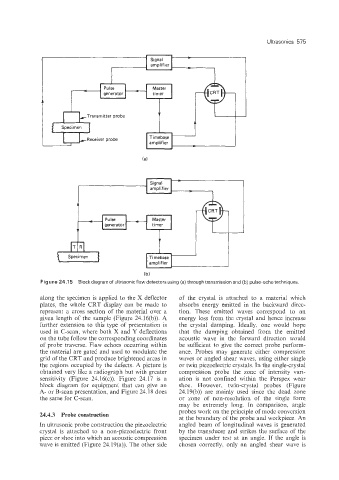
Figure 24.1 5 Block diagram of ultrasonic flaw detectors using (a) through transmission and (b) pulse-echo techniques.
along the specimen is applied to the X deflector of the crystal is attached to a material which
plates, the whole CRT display can be made to absorbs energy emitted in the backward direc-
represent a cross section of the material over a tion. These emitted waves correspond to an
given length of the sample (Figure 24.16(b)). A energy loss from the crystal and hence increase
further extension to this type of presentation is the crystal damping. Ideally, one would hope
used in C-scan, where both X and Y deflections that the damping obtained from the emitted
on the tube follow the corresponding coordinates acoustic wave in the forward direction would
of prlobe traverse. Flaw echoes occurring within be sufficient to give the correct probe perform-
the material are gated and used to modulate the ance. Probes may generate either compression
grid of the CRT and produce brightened areas in waves or angled shear waves, using either single
the regions occupied 'by the defects. A picture is or twin piezoelectric crystals. In the single-crystal
obtained very like a radiograph but with greater compression probe the zone of intensity vari-
sensitivity (Figure 24.16(c)). Figure 24.17 is a ation is not confined within the Perspex wear
block diagram for equipment that can give an shoe. However, twin-crystal probes (Figure
A- or B-scan presentation, and Figure 24.18 does 24.19(b)) are mainly used since the dead zone
the same for C-scan. or zone of non-resolution of the single form
may be extremely long. In comparison, angle
probes work on the principle of mode conversion
24.4.3 Probe construction
at the boundary of the probe and workpiece. An
In ultrasonic probe construction the piezoelectric angled beam of longitudinal waves is generated
crystal is attached to a non-piezoelectric front by the transducer and strikes the surface of the
piece or shoe into which an acoustic compression specimen under test at an angle. If the angle is
wave is emitted (Figure 24.19(a)). The other side chosen correctly, only an angled shear wave is