
Page 116 - System on Package_ Miniaturization of the Entire System
P. 116
Stacked ICs and Packages (SIP) 91
The third step in the thermal design of SIP is to understand the thermal characteristics
of SIP. There are two levels of thermal characterization. One is package-level thermal
characterization, and the other is system-level thermal performance. The package-level
thermal characterization can provide a better understanding of the package thermal
behavior due to different packaging architectures, thermal interface materials, and
operating environments. The JEDEC JC15 committee has defined several package-level
testing standards as described here:
• JESD51-2. Integrated Circuits Thermal Test Method Environment Conditions—
Natural Convection (Still Air) [2]. The purpose of this document is to outline
the environmental conditions necessary to ensure accuracy and repeatability
for a standard junction-to-ambient (q ) thermal resistance measurement in
A
natural convection.
• JESD51-6. Integrated Circuit Thermal Test Method Environmental Conditions—
Forced Convection (Moving Air) [3]. This standard specifies the environmental
conditions for determining thermal performance of an integrated circuit device
in a forced convection environment when mounted on a standard test board.
• JESD51-8. Integrated Circuit Thermal Test Method Environmental Conditions—
Junction-to-Board [4]. This standard specifies the environmental conditions
necessary for determining the junction-to-board thermal resistance, R , and
θJB
defines this term. The R thermal resistance is a figure of merit for comparing the
θJB
thermal performance of surface-mount packages mounted on a standard board.
All these testing standards are solely for the thermal performance comparison of one
package against another in a standardized environment. This methodology is not meant
to predict the exact performance of a package in an application-specific environment.
However, the data generated under these standard environments is very useful for
numerical model validation, for exchanging package thermal performance between
companies, and for quantification of the degradation in thermal performance post
reliability tests.
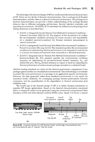
The fourth step in the thermal design of SIP is to utilize thermal simulations to
expedite SIP design optimization. Based on the thermal characterization mentioned
above, a numerical model can be generated using the commercial computational fluid
dynamics (CFD) and finite-element method (FEM) codes. Figure 3.10 shows a typical
Top epoxy Top BT Die
mold compound substrate attach Die
Top–flash, flash, spacer, SDRAM
Bottom–logic Interposer Air gap Bottom
+ Mold Bottom SB array
Top pkg SB compound BT substrate
(a) (b)
FIGURE 3.10 A typical example of a SIP thermal model. (a) Package cross-sectional view.
(b) Cross-sectional view of “quarter” thermal model.