
Page 113 - System on Package_ Miniaturization of the Entire System
P. 113
88 Cha pte r T h ree
FIGURE 3.5 Shear driven temperature cycle failure at a solder joint.
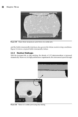
and the brittle intermetallic interfaces also govern the failure mode in drop conditions.
Figure 3.6 shows a typical brittle intermetallic failure.
3.2.3 Electrical Challenges
With the increased die or chip stacking, the density of I/O interconnections is increased
dramatically. Moreover, for high-performance requirements, the interconnect speed through
FIGURE 3.6 Failure of a solder joint during drop testing.