
Page 217 - System on Package_ Miniaturization of the Entire System
P. 217
Mixed-Signal (SOP) Design 191
4.4 Design of WLAN Front-End Module
Based on the aforementioned discussion on individual RF modules on LCP substrate,
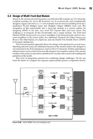
complete modules for use in RF front-end can be economically and systematically
designed. Figure 4.40 shows a 1 × 1 (one transmit and one receive) building block for a
dual-band WLAN Multple Input and Multiple Output (MIMO) front end. The
integration of this functionality into a front-end module is a critical enabler for
designing MIMO in the new, very small PCI Express Mini card form factor. The
challenge is to integrate all this functionality into a single module. The Front End
Module (FEM) incorporates two power amplifiers in the transmit paths and two low-
noise amplifiers in the receive paths, two additional Transmit (Tx) filters baluns, two
Receive (Rx) filter-baluns, two diplexers, and one Double Pole Double Throw (DPDT)
in 64 square millimeters.
The front-end module approach allows the design to be optimized in several ways.
Matching network losses are minimized because in the module interior the designer is
not restricted to the 50-Ω impedances used for the I/O terminals. Further performance
enhancements can be achieved because the designer has complete control of the precise
location of the passives and actives and therefore can take into account all coupling and
parasitics in the model.
This level of integration presents two conflicting design challenges. On the one
hand the desire for compact size requires unprecedented passive component density.
FIGURE 4.40 WLAN MIMO front-end building block.