
Page 219 - System on Package_ Miniaturization of the Entire System
P. 219
Mixed-Signal (SOP) Design 193
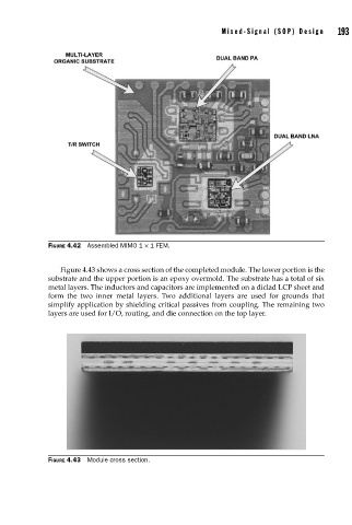
FIGURE 4.42 Assembled MIMO 1 × 1 FEM.
Figure 4.43 shows a cross section of the completed module. The lower portion is the
substrate and the upper portion is an epoxy overmold. The substrate has a total of six
metal layers. The inductors and capacitors are implemented on a diclad LCP sheet and
form the two inner metal layers. Two additional layers are used for grounds that
simplify application by shielding critical passives from coupling. The remaining two
layers are used for I/O, routing, and die connection on the top layer.
FIGURE 4.43 Module cross section.