
Page 228 - Sami Franssila Introduction to Microfabrication
P. 228
Wet-etched Silicon Structures 207
All silicon etchants etch aluminium, which means Table 21.1 Alkaline anisotropic etchants: some main
that either aluminum deposition has to be done after features of etchants
silicon etching, or aluminium has to be protected during
silicon etching. In some cases aluminum can be replaced Etchant KOH TMAH EDP
by another metal, such as gold. Some relief can be Rate (at 80 C) 1 0.5 1 (at 115 C)
◦
◦
achieved by saturating TMAH solution with silicon, but µm/min
typically only very short alkaline etchings are done after Typical concentration 40% 25% 80%
metallization. Selectivity (100):(111) 200:1 30:1 35:1
200:1 2000:1 10 000:1
Selectivity Si:SiO 2
Selectivity Si:Si 3 N 4 2000:1 2000:1 10 000:1
21.4 ETCH RATE AND ETCH STOP Etch stop factor 25 10 50
20
−3
(10 cm )
KOH rate can be made very high: the boiling point
of 50% KOH is ca. 150 C, which translates to
◦
ca. 10 µm/min etch rate for (100) planes. But in addi- in Table 21.1. Practical etch rates are in the range 0.5
tion to rate, other factors must be considered: surface to 1 µm/min.
roughness increases in alkaline etching beyond bond- Etch stop is an idealization; infinite selectivities are
ing quality, so the surfaces to be bonded must be not met with in the real world. High selectivity is termed
protected by oxide or nitride mask during KOH etch- etch stop when selectivity is so high that etch timing
ing. There have been experiments with ammonia etch- becomes non-critical. Etch stop can happen through
ing with arsenic oxide: etch rates of 1.5 µm/min at various mechanisms.
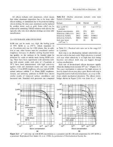
70 C have been demonstrated, with high selectivity Etch rate of boron-doped silicon decreases rapidly
◦
19
against oxide and aluminum masks and very smooth when the doping level exceeds 10 cm −3 (Figure 21.3).
surfaces, 2.4 nm RMS roughness, whereas typical KOH- The exact mechanism is unknown but high stresses in
etched surfaces exhibit 5 to 10 nm RMS roughness. heavily doped silicon may play a part. Boron etch stop is
Arsenic and antimony additions to KOH have shown frequently used in bulk micromechanics, as a way to fab-
similar results of improved surface smoothness and ricate simple mechanical structures. The silicon micro-
increased rate. Standard etch processes are compared bridge shown in Figure 2.1(b) was done by p ++ etch
10 2 10 2
78°C
(µm/h) (µm/h)
61°C
10 1 10 1
44°C
34°C
Silicon etch rate 10 0 KOH Etch rate 10 0 3.7 × 10 cm −3
19
concentration
19
10%
0
19
−3
4.0 × 10 cm
24% C = 3.8 × 10 cm −3
19
42% 4.2 × 10 cm −3
10 −1 57% 10 −1
〈100〉 silicon 〈100〉 silicon
60°C 24% KOH
10 −2 10 −2
10 17 10 18 10 19 cm −3 10 20 10 17 10 18 10 19 cm −3 10 20
Boron concentration Boron concentration
(a) (b)
Figure 21.3 p ++ etch stop: (a) with KOH concentration as a parameter and (b) with etch temperature for 24% KOH as
a parameter. Reproduced from Seidel, H. et al. (1990), by permission of Electrochemical Society Inc