
Page 69 - Lindens Handbook of Batteries
P. 69
2.26 PRINCIPLES OF OPERATION
and
I = t I sin( ω t + ) φ (2.53)
o
where E and E are the potentials at time t and 0
t
o
I and I are the currents at time t and 0
o
t
ω is the frequency in radians/s (equal to 2πf where f units are Hz)
Using Euler’s formula for trigonometric and complex functions, the impedance of the system can
be represented by the following complex relation, 25,26
E
Z() = ω = Z exp( ) = o j φ Z (cosφ o sin ) (2.54)
φ +
I
where j =-1. The components of Z(ω) thus consist of an imaginary part referred to as Z and a real
i
part referred to as Z . When plotting Z versus Z , one obtains a semicircle called a “Nyquist” plot,
i
r
r
as described below. Note that in the absence of capacitance and inductance, the Nyquist plot for a
simple resistor would be a simple vertical straight line with the intercept on the Z axis representing
r
the value of the resistor in ohms. For complex systems representing electrodes in cells and batter-
ies, the Nyquist plots can be interpreted in terms of various electrode-electrolyte parameters such
as solution resistance, kinetics (charge transfer), and capacitance; inductive effects are generally
not observed in these electrochemical systems. To relate the complex impedance of the electrode-
electrolyte interface to electrochemical parameters, it is necessary to model an equivalent circuit to
represent the dynamic characteristics of the interface. The model consists of a number of impedance
elements in networks based on series, parallel, or series/parallel combinations. For example, the total
impedance for n elements in series is given by
Z = Z + Z + Z + ⋅⋅⋅⋅+ Z (2.55)
total 1 2 3 n
For n elements in parallel, the impedance will be given by
1 1 1 1 1
= + + + ⋅⋅⋅⋅+ (2.56)
Z Z Z Z Z
total 1 2 3 n
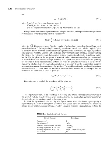
The important elements to be considered in modeling EIS data to electrodes are summarized in
Table 2.4. A realistic model will then allow one to determine the electrochemical parameters for an
electrode-electrolyte interface, which is discussed below.
In all of the equivalent circuits and Nyquist figures shown below, the double layer capacity is
represented by C, which is the symbol used for a pure (ideal) capacitor. However, due to surface
inhomogeneity and faradaic current (i.e., a “leaky” capacitor), for most electrochemical systems the
TABLE 2.4 Equivalent Circuit Elements
Circuit Element Impedance
Resistance, R R
Capacitance, C 1/Cjω
Constant phase element, Q (CPE) 1/Q ( jω) α
Warburg impedance, W (infinite) 1/Y( jω) 1/2
Warburg impedance, W (finite) tan [δD -1/2 ( jω) -1/2 ]/γ ( jω) 1/2
Inductance, L jωL