
Page 27 - MEMS Mechanical Sensors
P. 27
16 Materials and Fabrication Techniques
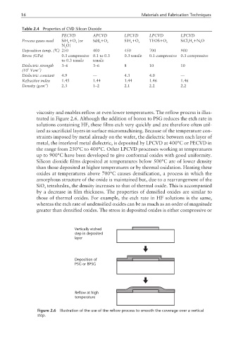
Table 2.4 Properties of CVD Silicon Dioxide
PECVD APCVD LPCVD LPCVD LPCVD
Process gases used SiH +O (or SiH +O SiH +O TEOS+O SiCl H +N O
4 2 4 2 4 2 2 2 2 2
N O)
2
Deposition temp. (°C) 250 400 450 700 900
Stress (GPa) 0.3 compressive 0.1 to 0.3 0.3 tensile 0.1 compressive 0.3 compressive
to 0.3 tensile tensile
Dielectric strength 3–6 3–6 8 10 10
–1
6
(10 Vcm )
Dielectric constant 4.9 — 4.3 4.0 —
Refractive index 1.45 1.44 1.44 1.46 1.46
–3
Density (gcm ) 2.3 1–2 2.1 2.2 2.2
viscosity and enables reflow at even lower temperatures. The reflow process is illus-
trated in Figure 2.6. Although the addition of boron to PSG reduces the etch rate in
solutions containing HF, these films etch very quickly and are therefore often util-
ized as sacrificial layers in surface micromachining. Because of the temperature con-
straints imposed by metal already on the wafer, the dielectric between each layer of
metal, the interlevel metal dielectric, is deposited by LPCVD at 400°C or PECVD in
the range from 250°C to 400°C. Other LPCVD processes working at temperatures
up to 900°C have been developed to give conformal oxides with good uniformity.
Silicon dioxide films deposited at temperatures below 500°C are of lower density
than those deposited at higher temperatures or by thermal oxidation. Heating these
oxides at temperatures above 700°C causes densification, a process in which the
amorphous structure of the oxide is maintained but, due to a rearrangement of the
SiO tetrahedra, the density increases to that of thermal oxide. This is accompanied
4
by a decrease in film thickness. The properties of densified oxides are similar to
those of thermal oxides. For example, the etch rate in HF solutions is the same,
whereas the etch rate of undensified oxides can be as much as an order of magnitude
greater than densified oxides. The stress in deposited oxides is either compressive or
Vertically etched
step in deposited
layer
Deposition of
PSG or BPSG
Reflow at high
temperature
Figure 2.6 Illustration of the use of the reflow process to smooth the coverage over a vertical
step.