
Page 145 - Make Your Own PCBs with EAGLE from Schematic Designs to Finished Boards
P. 145
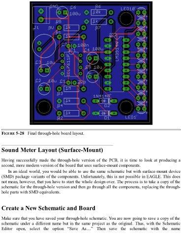
FIGURE 5-28   Final through-hole board layout.


  Sound Meter Layout (Surface-Mount)


  Having  successfully  made  the  through-hole  version  of  the  PCB,  it  is  time  to  look  at  producing  a
  second, more modern version of the board that uses surface-mount components.

      In an ideal world, you would be able to use the same schematic but with surface-mount device
  (SMD) package variants of the components. Unfortunately, this is not possible in EAGLE. This does
  not mean, however, that you have to start the whole design over. The process is to take a copy of the
  schematic for the through-hole version and then go through all the components, replacing the through-

  hole parts with SMD equivalents.


  Create a New Schematic and Board


  Make sure that you have saved your through-hole schematic. You are now going to save a copy of the

  schematic under a different name but in the same project as the original. Thus, with the Schematic
  Editor  open,  select  the  option  “Save  As…”  Then  save  the  schematic  with  the  name