
Page 232 - Microsensors, MEMS and Smart Devices - Gardner Varadhan and Awadelkarim
P. 232
212 MICROSTEREOLITHOGRAPHY FOR MEMS
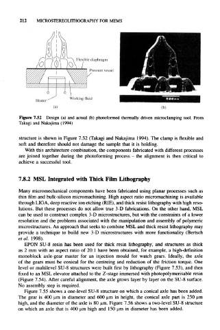
Figure 7.52 Design (a) and actual (b) photoformed thermally driven microclamping tool. From
Takagi and Nakajima (1994)
structure is shown in Figure 7.52 (Takagi and Nakajima 1994). The clamp is flexible and
soft and therefore should not damage the sample that it is holding.
With this architecture combination, the components fabricated with different processes
are joined together during the photoforming process - the alignment is then critical to
achieve a successful tool.
7.8.2 MSL Integrated with Thick Film Lithography
Many micromechanical components have been fabricated using planar processes such as
thin film and bulk-silicon micromachining. High aspect ratio micromachining is available
through LIGA, deep reactive ion etching (RIE), and thick resist lithography with high reso-
lutions. But these processes do not allow true 3-D fabrications. On the other hand, MSL
can be used to construct complex 3-D microstructures, but with the constraints of a lower
resolution and the problems associated with the manipulation and assembly of polymeric
microstructures. An approach that seeks to combine MSL and thick resist lithography may
provide a technique to build new 3-D microstructures with more functionality (Bertsch
et al. 1998).
EPON SU-8 resin has been used for thick resin lithography, and structures as thick
as 2 mm with an aspect ratio of 20:1 have been obtained, for example, a high-definition
monoblock axle-gear master for an injection mould for watch gears. Ideally, the axle
of the gears must be conical for the centreing and reduction of the friction torque. One
level or multilevel SU-8 structures were built first by lithography (Figure 7.53), and then
fixed to an MSL elevator attached to the Z-stage immersed with photopolymerisable resin
(Figure 7.54). After careful alignment, the axle grows layer by layer on the SU-8 surface.
No assembly step is required.
Figure 7.55 shows a one-level SU-8 structure on which a conical axle has been added.
The gear is 400 urn in diameter and 600 urn in height, the conical axle part is 250 urn
high, and the diameter of the axle is 80 urn. Figure 7.56 shows a two-level SU-8 structure
on which an axle that is 400 urn high and 150 urn in diameter has been added.