
Page 335 - Book Hosokawa Nanoparticle Technology Handbook
P. 335
FUNDAMENTALS CH. 5 CHARACTERIZATION METHODS FOR NANOSTRUCTURE OF MATERIALS
information from a small specimen area. By using any
Specimen spectral feature in an EEL spectrum, the change of this
Objective lens
feature’s intensity can be monitored simultaneously
with high spatial resolution over a broad area of the
specimen. Zero-loss filtering is done by simply select-
Intermediate lens ing the electrons over a narrow energy window that
includes only the zero-loss peak. The contribution of
inelastically scattered electrons to an image or diffrac-
Projection lens tion pattern leads to a blurring due to chromatic
aberration. Zero-loss filtering removes the contribution
of all inelastically scattered electrons to both images
and diffraction patterns. This is more serious for thicker
specimens; hence, zero-loss filtering will improve the
Entrance aperture
Energy Filter contrast and the resolution of such images considerably.
If an energy window at a somewhat higher energy-
CCD
loss is selected, the plasmon resonance peak that is
E -ΔE proportional to the number density of valence elec-
0
trons can be mapped. An efficient way to increase
contrast significantly is to find an energy range where
E 0 certain features can be clearly seen.
The most extensive analytical use of energy-filters
Energy Slit
is for core-loss imaging and elemental mapping. The
ability of an energy filter to show a 2D distribution of
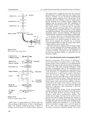
Figure 5.5.14
Post-column type energy filter. a specific element, integrated over the thickness of
the thin foil specimen, makes it a powerful tool for
analytical studies.
Condenser Lens
Condenser Aperture 5.5.3 Three-dimensional electron tomography (3D-ET)
Electron tomography (ET) consists of obtaining a
ObjectiveLens Specimen
3D reconstruction of an object from a series of pro-
Objective Aperture jection images. Data collection is accomplished by
tilting the specimen in the electron beam to produce,
Intermediate Lens as a tilt series. Like other imaging techniques, TEM
provides a translucent view of the specimen where
the details from different depths are superimposed in
Entrance aperture Image plane a 2D projection. A computational operation called
“back-projection” is then used to create a 3D object
from the tilt-series images. The back-projection
Ω Lens
algorithms project back the mass of the specimen
into the reconstruction volume. When this process is
repeated for a series of projection images from dif-
Achromatic
image plane ferent angles, back projected rays intersect and are
reinforced at the points where mass is found in the
Energy slit original structure. The rays pass through different
Projection Lens amounts of specimen mass producing a different
image for each angle.
The resolution and quality of the reconstruction
TV Camera
depends primarily upon two factors. First, the resolu-
Film,IP tion of tilt angle between successive images has a
CCD
dramatic effect upon reconstruction quality. The
smaller the tilt angle, the better is the reconstruction.
Figure 5.5.15 Second, the total tilt range determines the amount of
-type in-column energy-filter.
3D data “seen” over all tilt angles. The larger the total
tilt angle, the more data are seen in the reconstruction.
Both types of energy-filters are devices that can Generally, images are acquired at 1° 2°of tilt angle
form an image with electrons of only a small energy between successive images over a total tilt range of
range. The inelastic scattering process in EELS is about 60° 70°. A CCD camera is generally used
strongly localized, hence, it is used to obtain analytical for image acquisition. Radiation damage sets a limit
310