Page 105 - Rashid, Power Electronics Handbook
P. 105

6 The Power MOSFET                                                                                   91


                                                           V DD                                                V
                                                                                                                DD


                                                     I O            D                                     i
                                                                                                          O


                                                                                                   +  V  -
                                                                                                      DD

                                                                  +
                                                                                     i =
                                     i                                               G
                                     G                           V =V                 0
                                                             i    DS
                                                             D
                                 R                                DD                   R
                                  G                                                      G
                                                                  -
                    V GG =0                                                V GG =0

                                            (c)                                                    (d)
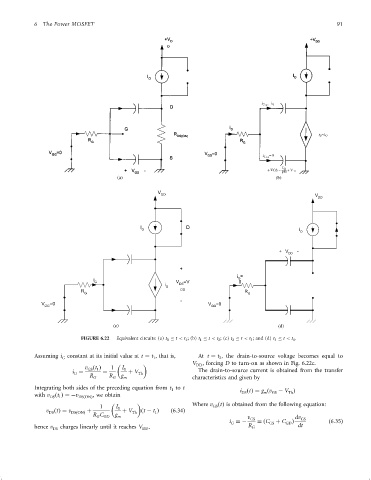
                                 FIGURE 6.22  Equivalent circuits: (a) t 0   t < t 1 ; (b) t 1   t < t 2 ; (c) t 2   t < t 3 ; and (d) t 3   t < t 4 .


                 Assuming i constant at its initial value at t ¼ t , that is,  At t ¼ t , the drain-to-source voltage becomes equal to
                                                                               2
                                                         1
                           G
                                                                      V  , forcing D to turn-on as shown in Fig. 6.22c.
                                                                       DD
                                  v ðt Þ   1   I 0
                                   GS 1
                              i ¼       ¼        þ V Th                 The drain-to-source current is obtained from the transfer
                               G
                                    R G   R G  g m                    characteristics and given by
                 Integrating both sides of the preceding equation from t to t         i ðtÞ¼ g ðv  ÿ V Þ
                                                               1
                 with v ðt Þ¼ÿv DSðONÞ , we obtain                                    DS      m  GS   Th
                       DS 1
                                                                      Where v ðtÞ is obtained from the following equation:
                                       1     I 0                             GS
                     v ðtÞ¼ v DSðONÞ  þ        þ V Th  ðt ÿ t Þ  ð6:34Þ
                      DS
                                                          1
                                     R C    g
                                      G  GD  m                                          v GS            dv GS
                                                                                  i ¼ÿ      ¼ðC GS  þ C GD Þ       ð6:35Þ
                                                                                   G
                 hence v  charges linearly until it reaches V  .                         R G             dt
                        DS                           DD
   100   101   102   103   104   105   106   107   108   109   110