
Page 195 - Semiconductor Manufacturing Handbook
P. 195
Geng(SMH)_CH13.qxd 04/04/2005 19:51 Page 13.18
PHYSICAL VAPOR DEPOSITION
13.18 WAFER PROCESSING
HF/RF HF/RF
power matching
supply network Pre-vacuum/
Base plate
Cooling water loading chamber
Shield Target Conveyor transport
system
Aperture
Residual gas
analyzer
Gas inlet
Palette Cooling
water
Vacuum pumps Load lock Load lock
Substrates
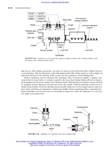
FIGURE 13.23 Schematic of a horizontal RF magnetron sputter machine with a loading chamber, multi-
ple targets, and a rotating substrate pallet.
and devices with complex geometries can easily be placed on the horizontal plate without need for
a special fixture. The key drawback is that bulk material that falls off the targets as well as flakes of
deposited material on the chamber walls can fall onto the substrates, contaminating them.
Vertical sputtering systems eliminate this drawback. They do however require a complex sub-
strate fixture to keep wafers or samples secured to the base plate without falling off and to ensure a
good thermal and electrical contact to the substrate holder. Bad electrical or thermal contact will lead
to variations in layer thickness and structure across the sample. Vertical sputtering systems exist as
simple linear designs where the substrate passes parallel along one or more targets and as rotary sys-
tems where substrates are mounted on a barrel-type holder. Vertical sputtering allows sequential mul-
tilayer deposition, but in most cases not simultaneous deposition, since the substrates can only face
one target at any given time.
Anode/palette
Cathode
Target Substrate
+ Target
+
Substrate Cathode
Anode/palette
+ +
+ +
FIGURE 13.24 Schematic of a horizontal and vertical sputter setup.
Downloaded from Digital Engineering Library @ McGraw-Hill (www.digitalengineeringlibrary.com)
Copyright © 2004 The McGraw-Hill Companies. All rights reserved.
Any use is subject to the Terms of Use as given at the website.