
Page 194 - Semiconductor Manufacturing Handbook
P. 194
Geng(SMH)_CH13.qxd 05/04/2005 18:03 Page 13.17
PHYSICAL VAPOR DEPOSITION
PHYSICAL VAPOR DEPOSITION 13.17
of the main chamber, since venting of the main chamber is not
required for substrate loading. The vacuum system is usually a
two-stage system with a mechanical coarse vacuum pump and a
turbo high vacuum pump. Ion current gauges are used to deter-
mine the process chamber pressure at high vacuum. A residual - -
gas analyzer is used to determine the concentration and compo- - -
sition of the residual gas. - -
-
Cooling Water. For chamber temperature control, a cooling N -
water system (dual-walled chamber or welded steel tubing) and S
a radiation heater is used. A good chamber design eliminates the N
possibility of cooling water entering the chamber and getting in
contact with electronics and current-carrying or high-voltage
parts in case of a leakage or system breakdown.
FIGURE 13.21 Schematic of mag-
netron sputter target, electromagnetic
Cathodes and Targets. Most systems have multiple cathodes
field, and subsequent cycloid path of
that allow the sputtering of two to four different materials in one
electrons. 5
run either simultaneously or sequentially. In addition to the
electrical switching network, a mechanical aperture/shutter sys-
tem is used to select between targets. That is, not only will an
“off” target not receive a sputtering voltage, it will also be mechanically sealed to prevent exposure
to accelerated Ar ions, reaction with the other sputtered material particles or simply mechanical chip-
ping of the target that leads to deposition of macroscale contamination particles on and in the
deposited layer.
Two standard configurations exist for the substrate holder and targets—horizontal and vertical
sputtering (Fig. 13.24). In both cases the distance between target and substrate is typically between
15 and 35 cm, depending on the target and palette sizes and geometries as well as the sputtering para-
meters. Horizontal sputtering allows for a simple substrate holder (e.g., rotating disc) that passes
underneath the targets. Most horizontal sputter targets have a circular shape with diameters between
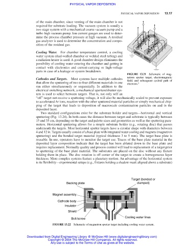
4 and 12 in. Targets usually consist of a base plate with integrated water cooling and magnets (magnetron
sputtering) and the bonded target material (typical thickness 3 to 5 mm). The target base plate is
reusable. In use, operators have to monitor the target use. Traces of the base plate material in the
deposited layer composition indicate that the target has been ablated down to the base plate and
requires replacement. Normally quality and process control will lead to replacement of a target prior
to sputtering of the base plate material. The substrates are placed on the disc without any fixture
holding them in place. The disc rotation is off center of the target to create a homogeneous layer
thickness. More complex systems feature a planetary motion. An advantage of the horizontal system
is its flexibility—experimental setups (e.g., fixtures holding a shadow mask aligned above a substrate)
Target (bonded or
Backing plate clamped)
Magnet assembly
Cathode body
Insulator
Shield
Cooling water lines
Bolt/screw
FIGURE 13.22 Schematic of magnetron sputter target including cooling water system.
Downloaded from Digital Engineering Library @ McGraw-Hill (www.digitalengineeringlibrary.com)
Copyright © 2004 The McGraw-Hill Companies. All rights reserved.
Any use is subject to the Terms of Use as given at the website.