
Page 190 - Semiconductor Manufacturing Handbook
P. 190
Geng(SMH)_CH13.qxd 04/04/2005 19:51 Page 13.13
PHYSICAL VAPOR DEPOSITION
PHYSICAL VAPOR DEPOSITION 13.13
Cooling water
Shield
Cathode
Target −
e − Metal, e.g., Al Positive column
Gas inlet
Ar
Plasma U DC
Ar +
Substrate
Cathode dark field
Substrate holder Al
+
Anode
To vacuum
system
FIGURE 13.15 Schematic of DC-sputtering equipment.
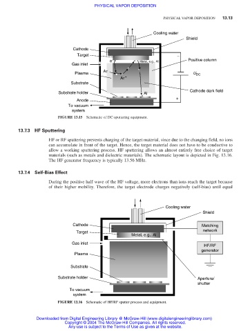
13.7.3 HF Sputtering
HF or RF sputtering prevents charging of the target material, since due to the changing field, no ions
can accumulate in front of the target. Hence, the target material does not have to be conductive to
allow a working sputtering process. HF sputtering allows an almost entirely free choice of target
materials (such as metals and dielectric materials). The schematic layout is depicted in Fig. 13.16.
The HF generator frequency is typically 13.56 MHz.
13.7.4 Self-Bias Effect
During the positive half wave of the HF voltage, more electrons than ions reach the target because
of their higher mobility. Therefore, the target electrode charges negatively (self-bias) until equal
Cooling water
Shield
Cathode Matching
network
Target
Metal, e.g., Al
Gas inlet
HF/RF
generator
Plasma
Substrate
Substrate holder Aperture/
shutter
To vacuum
system
FIGURE 13.16 Schematic of HF/RF sputter process and equipment.
Downloaded from Digital Engineering Library @ McGraw-Hill (www.digitalengineeringlibrary.com)
Copyright © 2004 The McGraw-Hill Companies. All rights reserved.
Any use is subject to the Terms of Use as given at the website.