
Page 237 - Separation process principles 2
P. 237
202 Chapter 6 Absorption and Stripping of Dilute Mixtures
other is the solute. For application to an absorber, let: the liquid, the solute concentration in the gas is always greater
than the equilibrium value, thus providing the driving force
L' = molar flow rate of solute-free absorbent for mass transfer of solute from the gas to the liquid. For the 4
V' = molar flow rate of solute-free gas (carrier gas) stripper, the operating line lies below the equilibrium line for 1
X = mole ratio of solute to solute-free absorbent in the the opposite reason. For the coordinate systems in Figure 6.8, I
liquid the operating lines are straight with a slope of L'/ V'. 4
1
Y = mole ratio of solute to solute-free gas in the vapor For an absorber, the terminal point of the operating line at :
the top of the tower is fixed at Xo by the amount of solute, if 1
Note that with these definitions, values of L' and V' remain any, in the entering absorbent, and the specified degree of 4
constant through the tower, assuming no vaporization of ab-
absorption of the solute, which fixes the value of Y1 in the '
sorbent into carrier gas or absorption of carrier gas by liquid. leaving gas. The terminal point of the operating line at "
For the solute at any equilibrium stage, n, the K-value is the bottom of the tower depends on YN+~ and the slope of
given in terms of X and Y as: the operating line and, thus, the flow rate, L', of solute-free
absorbent.
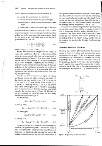
Minimum Absorbent Flow Rate
where Y = y/(l - y) and X = x/(l - x).
Operating lines for four different absorbent flow rates are
For the fixed temperature and pressure and a series of
values of x, equilibrium values of y in the presence of the shown in Figure 6.9, where each operating line passes
through the terminal point, (Yl, Xo), at the top of the column,
solute-free absorbent and solute-free gas are estimated by
and corresponds to a different liquid absorbent rate and cor-
methods discussed in Chapter 2. From these values, an equi-
responding slope, L'/ V'. To achieve the desired value of Yl
librium curve of Y as a function of X is calculated and plot-
for given YN+~, XO, and V', the solute-free absorbent flow
ted, as shown in Figure 6.8. In general, this curve will not be
rate L', must lie in the range of oo (operating line 1) to L&,
a straight line, but it will pass through the origin. If the solute
(operating line 4). The value of the solute concentration in
undergoes, in the liquid phase, a complete irreversible con-
the outlet liquid, XN, depends on L' by a material balance on
version by chemical reaction, to a nonvolatile solute, the
equilibrium curve will be a straight line of zero slope pass-
ing through the origin.
At either end of the towers shown in Figure 6.8, entering
and leaving streams and solute mole ratios are paired. For
the absorber, the pairs are (Xo, L' and Yl, V') at the top and
(XN, L' and YN+l, V') at the bottom; for the stripper, (XN+1,
L' and YN, V') at the top and (XI, L' and Yo, V') at the bot-
tom. These terminal pairs can be related to intermediate
pairs of passing streams by the following solute material bal-
ances for the envelopes shown in Figure 6.8. The balances
are written around one end of the tower and an arbitrary
intermediate equilibrium stage, n.
For the absorber,
or, solving for
Yn+i Xn(L1/ V') + Yl - Xo(L1/ V') (6-3)
For the stripper,
or, solving for Yn,
Yn = Xn+i (L'/ V') + Yo - XI (L'/ V') (6-5)
Equations (6-3) and (6-5), which are called operating-line
equations, are plotted in Figure 6.8. The terminal points of I
I Moles solute/mole solute-free liquid, X
these lines represent the conditions at the top and bottom of
xo XN
the towers. For the absorber, the operating line is above the (liquid in) (for Lmi,)
equilibrium line because, for a given solute concentration in Figure 6.9 Operating lines for an absorber,