
Page 188 - The Geological Interpretation of Well Logs
P. 188
- THE GEOLOGICAL INTERPRETATION OF WELL LOGS -
4030m DIP PLOT ===
— Summary scale logs
An extremely useful facility in dipmeter analysis, indeed
the analysis of any log, is to be able to change scales.
Compressed scale, summary dipmeter logs of 1:2000
to 1:5000 do two things. Firstly they allow a bulky docu-
ment at standard 1:500 or !:2G0 scales to be presented on
one A4 page, and secondly, they bring out large scale
4200m equally show only gradual changes. Such changes are
structural trends.
Frequently, structural dip varies gradually but consis-
tently through a well (Figure 12.30), For example, a
over several hundred metres, as the fault ig approached.
typical normal fault block shows slowly increasing dips
Drape of shale sequences over reefs or fault blocks will
brought out clearly in summary scale logs. Indeed, a
structural interpretation indicated on a summary scale
VECTOR
dipmeter log should be a standard document in any well
AZIMUTH
file: it will ensure that the dipmeter is used and that it
PLOT
contributes to routine analysis.
12.5 Dipmeter quality assessment.
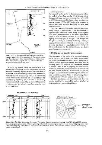
Figure 12.13 An azimuth vector plot and the corresponding
The assessment of the quality of a processed dipmeter
standard tadpole plot of the same interva]. The azimuth vector
log is essential: it affects the possibilities but especially
plot shows the nature of the structural break at 4128m much
more clearly than the tadpole plot. The plot is used in the the credibility of an interpretation. In very poor datasets,
analysis of unconformities and faults. there is often a high noise content. Noise dips have no
meaning and are a result of the computation method
(Cameron, 1992). Even on properly processed and fil-
Structural dip rotation should be available both as a
tered logs, core to log comparisons show that noise dips
bulk facility and as a zone facility, The sedimentary effect
are still present. However, interpretation routines are
described above only requires the zone with cross-beds to
designed to accommodate this and along with careful raw
be rotated. If an unconformity comes in the middle of a
data examination, noise effects on a final interpretation
well and the well is structurally tilted, it is useful to be
can be minimised. Quality assessment is essential.
able to rotate out the structural dips above and below the
Borehole conditions, data acquisition and data pro-
unconformity separately. Or to be able to structurally
cessing should all be assessed for quality: all affect an
Totate separate fault blocks. That is, it should be possible
interpretation and are considered below.
to rotate one dip and azimuth value from an entire well,
or one small zone.
PROGRESSIVE DIP REMOVAL
ORIGINAL LOG -10° ~28°
STEREOGRAM (POLAR)
ly oP sol lo be 60| lo DIP 60
~» 2] a
Be Bs xO
|
|
3000m
Structural dip
"Dip = 28°
‘~ é el. Azimuth = 295°
“
te as Pe %
Pe Te aL
3060m % | oxy
Figure 12.14 The effect of structura] dip rotation. The original dipmeter log shows a structural dip of 28°, azimuth 295°, seen on
the stereographic representation. Subtracting this dip and azimuth from the original log removes ai] structural dip (tog on the right)
while subtracting only 10° at 295° still leaves a substantial structural element. This routine is used, for example, in sedimentary
palaeocurrent analysis.
178