
Page 189 - The Geological Interpretation of Well Logs
P. 189
- THE DIPMETER -
Borehole quality (Waid, 1987) and dips can be seen to vary with rotation.
Poor borehole conditions affect the dipmeter probably Orientation data are averaged over a correlation interval
more than the other standard open hote tools. Hole in fixed interval routines (section 12.3), so that rapid tool
ovality causes pads to ‘float’, especially in deviated wells. Totation affects especially high dips and logs processed
A floating pad loses contact with the formation and shorts with broader parameters rather than small ones (it does
out into the mud. Caving may also cause pads to float and not affect manual picking). Tool rotation is quickly
is often the cause of tool sticking. judged from the compressed scale logs (Figure 12.15).
a
A good method of judging hole quality is to plot Sticking in poor borehole is serious for the dipmeter.
compressed scale dipmeter calipers (e.g. 1:5000), along Although the tool contains accelerometers and speed
with the dipmeter tool orientation data. When this is changes can be accounted for, serious sticking generally
done, intervals where data may be poor are quickly seen does not allow valid data to be collected. A tool which
(Figure 12.15). Frequently borehole wear can be seen sticks (stops moving) while the cable runs several metres
on these plots, the nearer the hole to TD the better the and then jerks free, will be noticed on both the tension
condition, the lower parts having been less exposed to and the featureless curves gained during the stuck period
drilling wear. Alternatively, detailed 1:20 or 1:50 scale (Figure 12.16). Speed correction will attempt to discount
pilots are found to be useful in indicating where dipmeter the data when the tool is stuck and expand the data
curves mimic the calipers, as occurs in small scale riffling collected as the tool jerks free. However, when sticking
(R.Trice, pers. comm.). Although calipers are normally is serious, there will be no valid data.
plotted with the processed dipmeter results, prior As a check on the orientation calibration of the dip-
examination helps the processing itself. meter tool, which can cause problems, it is useful to
compare dipmeter derived hole deviation with the quite
Data acquisition
independent directional surveys measured during drilling.
Quality assessment at the acquisition stage concerns tool
performance during logging and tool calibration. Tool
Processing quality
rotation, sticking and curve activity are indicative of
Most processing software has built-in quality indicators.
performance. A tool should not rotate more frequently
That is, tadpoles are plotted with filled or open heads
than one turn per 15 m (50'), as this can affect processing
representing good or bad data. This assessment is gener-
ally statistical. However, the limit between good and bad
HOLE
data, as printed on the log, can generally be varied at will.
GR DEPTH X & ¥ CALIPERS DEV. P1 AZIMUTH
9 150 m 5” 26"0° 19° 0° 360°
¥
¢
>] 4400
=
CORRELATION RESISTANCE CALIPERS TENSION
ohm
x
2 20 16"|2500 6100
1
r
4450
2840m
4588 = | legging
values
no tool
normal
4558 —] rotation
real
oval hale \
scale
4600 |
8 3 3 a
rt
oO ° toal-to = o 8 ec 3
4650 |
where stuck stuck
value tool teal
4726
on-gauge
hole
4758
5° deviation rotating teal _ i =
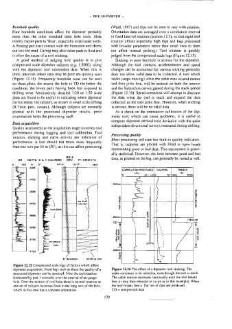
Figure 12.15 Compressed scale logs of factors which affect
dipmeter acquisition, From logs such as these the quality of a Figure 12.16 The effect of a dipmeter tool sticking. The
processed dipmeter can be assessed. Note the tcol rotation cable continues to be reeled in, even though the tool is stuck.
(indicated by pad | azimuth) over the interval of on-gauge The cable tension increases continually until the tool breaks
hole, Over the section of oval hole there is no tool rotation as free (it may then rebound or yo-yo as in this example). When
one set of calipers becomes fixed in the long axis of the hole, the tool breaks free a ‘flat’ set of data are produced.
which in this case has a constant orientation. CD = compressed data
179