
Page 27 - The Geological Interpretation of Well Logs
P. 27
- THE LOGGING ENVIRONMENT —
ELECTRICAL
“o
7
4 Induction
ie
original log Laterologs
LL le;
biocked log SL Sphericalty
focused
MSFL Micrologs
BHC ACOUSTIC
NUCLEAR
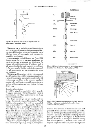
Figure 2.14 The effect of blocking on log data. Note the
reallocation of ‘transition’ values.
CNL Neutron
The method can be applied to several logs simultane-
ously so that they all become perfectly comparable (Serra
LBL 4 Density
and Abott, 1980) and the problems of comparing logs of
differing depths of investigation and bed-resolving (
capabilities are eliminated.
PEF Photoelectric
A more complex method (Kerzner and Frost, 1984)
does not assume that the raw log values are adequate, and
tries to compensate for assumed tool deficiencies. For
instance, it is well known that the SP will only reach its scale approximate
full value and reat deftection in very thick beds (Chapter Figure 2.15 Investigation geometry of various logging tools
5). The more complex blocking method tries to approach (modified from Desbrandes, 1968 and Serra, }979).
this full value from the raw log values using the known
RADIAL DISTANCE
tool limitations.
100 inchos
60
The squaring of logs certainly gives a nearer approach
Resistive
to real formation values and formation aspects and can be
a great aid to geological interpretation. Additionally, with
the increasing use of logs on the computer, squaring is
essential to bring all logs to comparable sensitivities so as
to allow valid comparisons and cross-plotting: this is not
always done.
Geometry of investigation Conductive
BOREHOLE
It would be natural to assume that a tool generally
investigates a spherical volume of formation. However,
this is rarely the case. There are two reasons; tool design
and formation interaction.
Tool design and too] type are very variable, each tool
having a characteristic volume of investigation. Through Figure 2.16 Formation influence on electrical tool response
the book, in the chapters where each tool is described, (SFL) at a resistive to conductive bed boundary (from
these characteristics will be discussed for the tool in Anderson and Chew, 1985).
question. In this section it will simply be pointed out that
these differences in investigating characteristics exist medium. The formation influence is consistent and
(Figure 2.15). There is an inherent difference between the predictable. In the subsurface, unfortunately, tt is neither.
volumes investigated by resistivity logs, acoustic logs and This was touched upon when depth of investigation was
by nuclear logs because of the geophysical differences in considered previously, the neutron tool being shown to
the measurements. The behaviour of an ion in a formation have a greater depth of investigation in the absence of
is quite different from the behaviour of a gamma ray. porosity, the volume of investigation therefore varying
When the volume of investigation of a tool is measured with porosity (Table 2.2). In other words, formation
in the laboratory, it is generally for a pure, homogeneous response is dynamic rather than passive and especially
17