
Page 28 - The Geological Interpretation of Well Logs
P. 28
- THE GEOLOGICAL INTERPRETATION OF WELL LOGS -
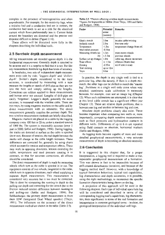
complex in the presence of heterogeneities and often Table 2.5 *Factors affecting wireline depth measurements.
unpredictable. For example, for the resistivity logs, when *figures for heptacable at 3000m (from Theys, 199] and Sgllie
and Rodgers, 1994).
a resistive bed and a conductive bed are in contact, the
conductive bed tends to act as a sink for the electrical Factor Potential | Remarks
current which flows preferentially into it. Current fields error
around the boundary are distorted and the precise tool (metres)
response difficult to define (Figure 2.16).
Elastic stretch 3.0m incudes cable twisting
These effects will be discussed more fully in the
Inelastic stretch 2.0m first runs only
chapters describing the individual tools.
Temperature -1.5m temperature change from ref.
Mud radial pressure -0,75m
Measuring wheels (a) | l-3m more recent wheels
2.5 Borehole depth measurement
(b) | 1.5-3m previous wheels
All log measurements are recorded against depth: it is the Surface set-up changes | {.0m cable sag, sheave movement
fundamental measurement. Generally depth is assumed to Tidal effects + 1.5m | offshore (North Sea)
Zeroing -0.25m not if zero in mud
be accurate and it is a surprise to find that it is not. But Hike
up to 12m
Tool sticking
any measurement, borehole log depth has limits of accuracy.
Yoyo 0.6m
In boreholes, two sets of independent depth measure-
ment exist side by side; ‘loggers depth’ and ‘drillers
In practice, the depth in any single well is tied to a
depth’. Driller’s depth, considered to be the least
particular log, often the density. If there is a depth mis-
accurate, is constructed by measuring with a tape
match, the other logs can be shifted to match the ‘master
measure the lengths or stands of dnl] pipe as they are run
log’. Problems in a single well only come when very
into the hole and simply adding up the lengths.
detailed, centimetre scale calibration is necessary
Corrections are seldom applied to these measurements
between, for example, core and an image log (Chapter
and human error not unusual. Lengths of drill-pipe are
13}. When such calibrations are attempted, it is clear that
easily ‘forgotten’. Logger’s depth, generally the more
at this level cable stretch has a significant effect (see
accurate, is measured with the wireline cable. There are
Chapter 13). These are relative depth problems, that is
two ways, by using magnetic markers on the cable and by
between one log and another or between log and core.
direct measurement with an odometer. The direct
Absolute depth problems clearly also exist. These
measurement generally supplies the primary depth. The
become important when comparing two wells or, more
two wireline measurement methods are briefly described.
importantly, comparing depth sensitive measurements
Magnetic markers are placed on a cable by the logging
such as fluid pressures and hydrocarbon contacts in
company every 100 feet or 25 m, under a standard tension
different wells. Differences of up to 6 m are reported
of 1000 Ibs. The system is reasonably accurate (error ]
using fluid contacts as absolute, horizontal markers
part in 5000; Sgllie and Rodgers, 1994). During logging,
(Sgllie and Rodgers, 1994).
the marks are detected at surface as the cable is spooled
As logging tools become capable of more and more
(in or out). Because of tension, the real depth between the
detailed geophysical measurements, a very accurate
marks will change as the cable length increases. These
measurement of depth is becoming an absolute necessity,
differences are corrected for, generally by using charts
which account for tension and temperature effects. These
2.6 Conclusion
may work in opposing directions, tension extending the
cable, temperature and mud pressure causing it to {t is suggested in this chapter that, for a proper
contract, so that for accurate corrections, all effects interpretation, a logging 100] is required to make a true,
should be considered. repeatable geophysical measurement of a formation.
The direct measurement of depth is made by measuring This was shown in fact to be impossible because of
wheels which turn as the cable is spooled in or out. The drill-created disturbances (invasion), and because of the
equipment consists of two wheels, tangential to the cable, Jogging method itself. However, with a knowledge of
which turn in opposite directions, each wheel supplying a typical formation behaviour, typical tool capabilities,
separate depth measurement. This measurement is log characteristics and depth accuracies, it is possible,
considered very accurate but it too must be corrected. using the right methodology, to reconstruct the specific
This is done by comparing the running-in depth to the formation characteristics being shown on the log.
pulling-out depth and correcting for the stretch due to the A projection of this approach will be used in the
friction induced tension difference between running-in following chapters. Each type of individual open-hole log
and pulling-out (S¢llie and Rodgers, 1994). For will be considered and described in terms of the
Schlumberger, the primary depth measurement is from corresponding logging tool’s capabilities, log characteris-
their [DW (Integrated Dual Wheel spooler) (Theys, tics, their significance in terms of the rea] formation and
1991). The influences on the accuracy of the direct interpretation in common geological terms — in short, the
measurement method are shown in the table (Table 2.5). geological interpretation of the individual well logs.
18