
Page 84 - The Ultimate Palm Robot
P. 84
Color profile: Generic CMYK printer profile
Composite Default screen
Bots /The Ultimate Palm Robot/ Mukhar & Johnson / 222880-6 / Chapter 3
Chapter 3 Building the Robot 67
memory location has an address. When a block of memory is used, the
first location has a particular address, the next location is at address+1,
the next location is address+2, etc. Thus, the first location is address+0.
And that’s why computer geeks who go to football games can be heard
to yell, “We’re number zero!”
Using the three wire assemblies, connect Sensor 1 to Port 0, Sensor 2 to Port
1, and (can you guess what’s coming?) Sensor 3 to Port 2. Note that the white
connector can only be inserted one way: there is a small tab on the housing
that fits into a slot on the sensor connector. On the controller board, there are
no tabs and slots to help you get lined up. So, ensure the ground wire (the
black wire, if you’re using color coding), is closest to the board, and attach the
connector to the posts.
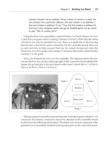
Now, you’ll attach the servos to the controller. The digital ports for the ser-
vos are the four sets of pins at the top right of the controller board labeled H4.
Again, the ground pin is the pin closest to the board. Attach Servo 1 to Port 0,
Servo 2 to Port 1, Servo 3 to Port 2.
The last connections to be made are from the AAbattery pack and the 9-volt
connector. The battery connectors should be attached to the controller board
as shown in the following illustration. The black wire of each connector is the
ground wire; it should be attached to the ground pins on the controller board.
P:\010Comp\Bots\880-6\ch03.vp
Monday, May 12, 2003 4:41:30 PM