
Page 564 - DSP Integrated Circuits
P. 564
12.6 INTERPOLATOR, Cont. 549
RAM. The area of the first RAM, with eight words of which only five are used, is
estimated as
ARAMI = 0.5 • 0.14 « 0.07 mm 2
The area for the second RAM, with 16 words of which only 10 are used, is esti-
mated as
2
ARAM2 = 0.5 • 0.2 = 0.1 mm
Of course, the unused cells in the memories and the corresponding parts of
the address decoders are never implemented. The corresponding floor plan is
shown in Figure 12.18. The interpolator requires 16 input pins, 16 output pins,
and at least 3 pins for communication and clocking. We will use 4 VDD and 4 Gnd
pins. Further, we assume that 5 pins are needed for testing purposes. Thus, alto-
gether we need about 48 pins. The floor plan for the interpolator is shown in Fig-
ure 12.19.
Figure 12.17 Dual-port RAM with 8 x 21 bits
Drivers
n l Write Port I n t
RAM Core |
<N
O
\^ I Read P 0rt I / v
Write Address Decoder Read Address Decoder
0.5 mm
^ ^
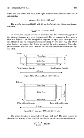
Figure 12.18 Dual-port RAM with 16 x 21 bits
2
The active circuitry is about 1.1 x 1.9 mm = 2.1 mm . The pads can not be
placed with a spacing of less than 135 um. Hence, the die can accommodate only