
Page 62 - DSP Integrated Circuits
P. 62
2.3 MOS Logic 47
To estimate junction temperature for an air-cooled integrated circuit, it is nec-
essary to know the ambient air temperature, TA, the air velocity, 0, and the ther-
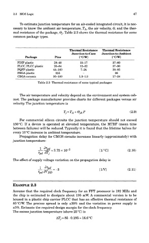
mal resistance of the package, Qj. Table 2.3 shows the thermal resistance for some
common package types.
Thermal Resistance Thermal Resistance
Junction-to-Case Junction-to-Ambient
Package Pins [°C/W] [°C/W]
PDIP plastic 28-48 15-17 37-60
PLCC, PLCC plastic 20-84 12-32 37-90
PQFP plastic 44-160 7-24 30-85
PBGA plastic 225 - 26
CBGA ceramic 95-180 1.3-1.9 17-24
Table 2.3 Thermal resistance of some typical packages
The air temperature and velocity depend on the environment and system cab-
inet. The package manufacturer provides charts for different packages versus air
velocity. The junction temperature is
For commercial silicon circuits the junction temperature should not exceed
150 °C. If a device is operated at elevated temperature, the MTBF (mean time
between failures) will be reduced. Typically it is found that the lifetime halves for
every 10 °C increase in ambient temperature.
Propagation delay for CMOS circuits increases linearly (approximately) with
junction temperature:
The effect of supply voltage variation on the propagation delay is
EXAMPLE 2.3
Assume that the required clock frequency for an FFT processor is 192 MHz and
the chip is estimated to dissipate about 195 mW. A commercial version is to be
housed in a plastic chip carrier PLCC that has an effective thermal resistance of
85°C/W. The process spread is only ±30% and the variation in power supply is
±5%. Estimate the required design margin for the clock frequency.
The excess junction temperature (above 25°C) is
AT, = 85-0.195 = 16.6 °C